IEC 60730 Certification Process: From Gap Analysis to Certificate Acquisition
Introduction
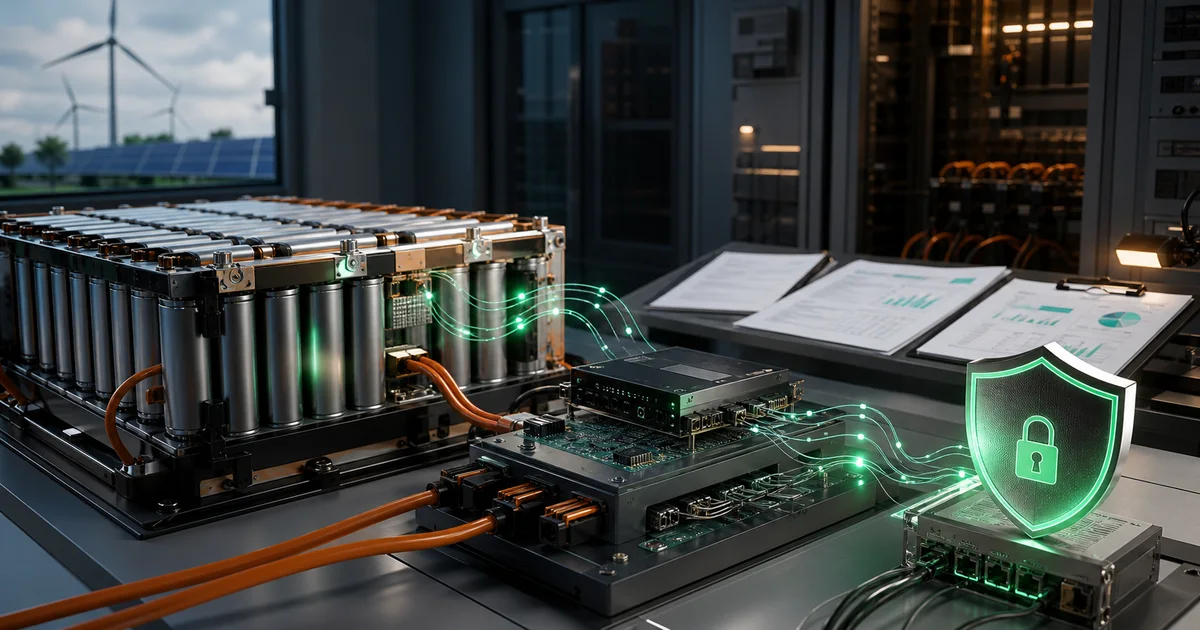
For household and similar electrical automatic controls, IEC 60730-1 Annex H functional safety certification serves as an essential passport to international markets. Particularly for applications such as energy storage systems and battery management systems (BMS), referenced standards like UL 9540, UL 1973, and IEC 62619 explicitly require controllers to comply with Class B functional safety requirements.
This article systematically introduces the complete IEC 60730 Annex H certification process, covering 11 key phases from project initiation to certificate acquisition. It aims to help product managers and certification leads comprehensively understand the certification path and effectively plan timeline and resources.
I. Certification Overview and Value
1.1 What is IEC 60730 Annex H
IEC 60730-1 is the international standard for household and similar electrical automatic controls, with Annex H specifying functional safety-related requirements. This annex specifically addresses controllers using software, proposing systematic requirements for fault detection and control techniques.
Core Concepts:
| Concept | Description |
|---|---|
| Class A | Control functions not safety-dependent (e.g., room temperature regulation, display) |
| Class B | Control functions preventing unsafe states (e.g., over-temperature, over-voltage protection) |
| Class C | Control functions preventing special hazards (e.g., explosion protection) |
1.2 Market Value of Certification
| Market Region | Certification Requirement | Referenced Standard |
|---|---|---|
| European Union | CE mark + LVD Directive | EN 60730-1 |
| North America | UL certification/ETL certification | UL 60730-1 |
| International | CB certification | IEC 60730-1 |
| China | CCC certification (selected products) | GB 4706.1 reference |
1.3 Typical Application Scenarios
Energy Storage Systems (ESS):
- Battery Management System (BMS) protection functions
- Overcharge, over-discharge, over-temperature, over-current protection
- Charging control system safety functions
Home Appliance Control:
- Water heater over-temperature protection
- Air conditioner compressor protection
- Motor overload protection
II. Complete Certification Process (11 Phases)
┌─────────────────────────────────────────────────────────────────────────────────┐
│                     IEC 60730 Functional Safety Certification Process            │
└─────────────────────────────────────────────────────────────────────────────────┘

    0.Project Initiation  1.Information Gathering 2.Risk Assessment   3.Document Review
    ├─Project email       ├─Send document list   ├─FMEA analysis      ├─Completeness check
    ├─Confirm PM          ├─Kick-off meeting     ├─Class classification├─Consistency verification
    └─Define scope        └─Document receipt     └─Safety function ID └─Compliance audit
                                                                 ↓
    8.Report Preparation←7.System Integration   ←6.Test Verification←5.HW/SW Evaluation
    ├─Draft writing       ├─Interface testing    ├─Fault injection     ├─Hardware evaluation
    ├─Internal review     ├─Safety function      ├─Black/white box     ├─Software evaluation
    ├─Client confirmation verification           └─Timing tests        └─Architecture review
         ↓                  ↓                  ↓                  ↓
    9.Certification Decision 10.Project Archival  11.Lessons Learned
    ├─Report signing        ├─Document organization├─Case analysis
    ├─Label confirmation    └─Record archiving    └─Process improvement
    └─Certificate delivery
Phase 0: Project Initiation
Trigger Condition: Receipt of project initiation email or certification requirement confirmation
Key Activities:
-
Confirm Product Information
- Product name and model
- Application scenarios (BMS, energy storage systems, home appliances, etc.)
- Target markets (European Union, North America, international)
-
Determine Applicable Standards
Market Region Standard Version International/Europe IEC 60730-1 2022 edition (current latest) North America UL 60730-1 2024 edition China GB 4706.1 References 60730 requirements -
Develop Assessment Plan
- Assessment scope definition
- Key milestone setting
- Resource requirement evaluation
- Timeline planning
Deliverable: Assessment Plan
Phase 1: Information Gathering
Key Activities:
-
Send Document List
Required documents include:
Document Category Specific Documents Purpose Product Information Product specification, functional description Understand product functions Hardware Documents Circuit schematics, PCB layout, BOM Hardware design assessment Software Documents Software architecture diagrams, flowcharts, test reports Software compliance assessment Safety Analysis FMEA reports, risk assessment reports Safety function confirmation -
Kick-off Meeting
Meeting agenda:
- Project background introduction
- Assessment scope confirmation
- Document list explanation
- Technical question communication
-
Document Receipt and Preliminary Check
Check points:
- Document version consistency
- Information completeness
- Key information clarity
Deliverables: Document receipt checklist, kick-off meeting minutes
Phase 2: Risk Assessment
Key Activities:
-
Identify Safety Functions
Common safety function identification:
Safety Function Risk Scenario Recommended Class Overcharge protection Battery overcharge leading to thermal runaway Class B Over-temperature protection Battery thermal runaway Class B/C Over-current protection Circuit overheating, equipment damage Class B Over-discharge protection Battery damage, leakage Class B -
Conduct FMEA Analysis
Analysis process:
Identify system components → Analyze failure modes → Evaluate failure effects ↓ ↓ ↓ Determine risk level → Design detection mechanisms → Complete FMEA report -
Determine Class Level
Decision process:
Can failure directly cause hazards (e.g., explosion)?
├─ Yes → Class C
└─ No → Continue evaluation
Can failure cause unsafe states?
├─ Yes → Class B
└─ No → Class A
Deliverables: FMEA analysis report, safety function list, Class classification table
Phase 3: Document Review
Review Dimensions:
-
Hardware Document Review
- Circuit schematic completeness
- Protection circuit design rationality
- PCB layout compliance with safety requirements
- BOM specification completeness
-
Software Document Review
- Software architecture diagram clarity
- Flowchart coverage of key functions
- Test report completeness
-
Cross-document Consistency Check
Check Item Document A Document B Consistency Confirmation MCU model Schematic BOM ☐ Software version Flowchart Test report ☐ Function definition Specification FMEA ☐
Deliverables: Document review report, non-compliance list
Phase 4: Hardware Evaluation
Evaluation Focus:
-
MCU/Processor Evaluation
- Architecture type (Harvard/Von Neumann)
- Memory architecture and test methods
- Clock system and monitoring mechanisms
-
Circuit Design Evaluation
- Power circuit integrity
- Input/output circuit protection
- Communication interface security
-
Table H.1 Compliance Check
Item-by-item verification of standard requirements:
Clause Requirement Evidence Compliance H.1 Protection measure test description Test plan ☐ H.2 Other control effect description Design document ☐ H.3 Software sequence documentation Flowchart ☐
Deliverables: Hardware evaluation record form, Table H.1 compliance checklist
Phase 5: Software Evaluation
Evaluation Content:
-
Software Architecture Review
Software structures available for Class B:
Structure Type Description Recommendation Single channel + periodic self-test Minimum requirement ★★★ Single channel + periodic self-test + monitoring Enhanced ★★★★★ Dual channel structure High reliability ★★★★ -
Key Mechanism Evaluation
Mechanism Evaluation Points Common Issues Watchdog Independent clock source, timeout setting Same clock source as CPU Program flow monitoring State machine, logic checking Lack of monitoring Memory testing CRC, March testing Only tested at startup Input validation Range checking, reasonableness checking Lack of validation -
Fault Detection Time Evaluation (H.8)
Safety Function Fault Type Detection Method Declared Detection Time Allowed Fault Time Over-temperature protection Temperature sensor fault Dual channel comparison 100ms 500ms Over-current protection Current detection fault Reasonableness check 50ms 200ms
Deliverables: Software evaluation record form, fault detection time declaration table
Phase 6: Test Verification
Test Types:
-
Fault Injection Test
Fault Type Injection Method Expected Response Pass Criteria Flash fault Simulate bit flip CRC detection failure Detect and respond RAM fault Modify memory content Memory test detection Detect and respond Clock fault Change clock frequency Frequency monitoring trigger Detect and respond Watchdog Disable watchdog feeding System reset Normal reset Input stuck Fix input value Reasonableness check Detect and respond Output short Short output Feedback detection Detect and respond -
Functional Test
- Normal function test
- Boundary condition test
- Abnormal condition test
- Timing test
-
EMC Test Verification
Class B minimum requirement: Test Level 3
Test Item Level 3 Requirement Importance Voltage dip/interruption Specific cycles Must pass Surge immunity Specific voltage Must pass EFT/Burst Specific frequency Must pass Electrostatic discharge Contact/air discharge Must pass
Deliverables: Fault injection test report, test waveform records
Phase 7: System Integration Evaluation
Evaluation Content:
-
Hardware-Software Interface Test
- GPIO configuration correctness
- Interrupt triggering and response
- Timer configuration
-
System Function Verification
- All safety functions work properly
- Fault detection mechanisms effective
- Fault response correct
-
Safety Function Integration Test
Test scenarios:
Scenario 1: Normal operation → Fault occurs → Fault detection → Safety response → System reset
Scenario 2: Multiple faults occur → Fault detection priority → Safety response
Scenario 3: Normal operation → EMC interference → Fault detection → Safety recovery
Deliverables: System integration evaluation report, interface test records
Phase 8: Report Preparation
Report Structure:
1. Project Information
   - Product information, client information, assessment standard, assessment scope

2. Assessment Summary
   - Product overview, safety function list, assessment conclusion

3. Assessment Process
   - Assessment methods, assessment basis, assessment process

4. Detailed Assessment
   - Hardware evaluation, software evaluation, system integration evaluation, test verification

5. Table H.1 Compliance Declaration

6. Safety Function Evaluation
   - Detailed evaluation of each safety function

7. Non-compliance Handling

8. Assessment Conclusion
   - Compliance declaration, usage restrictions (if any)

9. Attachments
   - Document list, test records, waveform diagrams
Review Process:
- Technical review: Peer engineer review
- Expert review: Senior engineer/expert review
- Approval: Authorized signatory approval
Deliverable: Functional Safety Assessment Report (official version)
Phase 9: Certification Decision
Key Activities:
-
Label Information Confirmation
Product Model: XXX Rated Voltage: XXX Rated Frequency: XXX Certification Mark: [Applicable Mark] -
Certificate Delivery (if applicable)
- CB certificate (international certification)
- CE declaration of conformity
- UL certification certificate (North America)
-
Project Closure
- Report signed and issued
- Certificate delivered
- Client confirmed
Deliverables: Assessment certificate, label confirmation letter
Phase 10: Project Archival
Archival Structure:
ProjectNumber_ProductName/
├── 01_Administration/     # Administrative files
├── 02_Product/            # Product materials
├── 03_Hardware/           # Hardware documents
├── 04_Software/           # Software documents
├── 05_Safety_Analysis/    # Safety analysis
├── 06_Test_Reports/       # Test reports
└── 07_Assessment/         # Assessment files
Archival Requirements:
- Document naming conventions
- Retain all communication records
- Preserve test raw data
Phase 11: Lessons Learned
Summary Content:
-
Case Analysis
- Project characteristics (technical challenges, innovations)
- Challenges during assessment
- Solutions
-
Process Improvement Suggestions
- Assessment method improvements
- Document template optimization
- Tool/equipment requirements
-
Knowledge Base Contribution
- Typical non-compliance cases
- Best practices
- Technical solutions
III. Key Milestones and Deliverables
| Milestone | Phase | Deliverables | Review Requirements |
|---|---|---|---|
| Project Initiation | Phase 0 | Assessment Plan | PM confirmation |
| Kick-off Meeting | Phase 1 | Meeting minutes + material confirmation | Both parties signed |
| Risk Assessment Complete | Phase 2 | FMEA report + Class classification table | Internal review |
| Document Review Complete | Phase 3 | Document review report | Non-compliance items cleared |
| Assessment Complete | Phase 4-5 | Assessment data records | Technical review |
| Test Verification Complete | Phase 6 | Test reports + waveform records | Witnessed testing |
| Report Issuance | Phase 8-9 | Official assessment report | Multi-level review |
IV. Common Issues and Response Strategies
4.1 High-Frequency Non-compliances
| Issue Number | Issue Description | Solution | Priority |
|---|---|---|---|
| NC-01 | Program memory tested only at startup | Add runtime periodic testing | High |
| NC-02 | Watchdog shares clock source with CPU | Use independent clock source | High |
| NC-03 | Class B function incorrectly classified as A | Re-evaluate function classification | High |
| NC-04 | Fault detection time not declared | Supplement H.8 declaration | High |
| NC-05 | Improper watchdog feeding position | Adjust watchdog feeding logic | Medium |
| NC-06 | Lack of input validation | Add range/reasonableness checking | Medium |
| NC-07 | EMC test level insufficient | Upgrade to level 3 | High |
| NC-08 | RAM test destroys data | Use non-destructive testing | Medium |
| NC-09 | Communication without verification | Add CRC/Checksum | Medium |
| NC-10 | No code review records | Provide code review evidence | Low |
4.2 Client Communication Points
Common Q&A:
| Question | Key Response Points |
|---|---|
| Why is FMEA needed? | Required by IEC 60730 H.5.1, it’s the basis for identifying safety functions and determining Class levels |
| Is fault injection testing mandatory? | Yes, it’s the only method to verify fault detection mechanism effectiveness, required by standard H.2.3 |
| Is watchdog mandatory for Class B? | Not mandatory, but typically needed. Alternatives: program flow monitoring, external clock monitoring |
| Can documentation be simplified? | Must meet Table H.1 minimum requirements, but depth can be adjusted based on actual conditions |
4.3 Technical Challenge Responses
Scenario 1: Complex System Assessment
- Issue: Multi-MCU systems, distributed architecture
- Solution: Modular assessment, focus on safety-related paths
Scenario 2: Remote Software Update
- Issue: UL 9540 Section 16.2 requirements
- Solution: Assess update authorization, verification, recovery mechanisms
Scenario 3: Multi-standard Certification
- Issue: Same product, multiple standards
- Solution: Analyze differences, determine strictest requirements, coordinate assessment plan
V. Time and Cost Estimation
5.1 Typical Project Cycles
| Project Type | Initial Assessment | Update Assessment | Extension Assessment |
|---|---|---|---|
| Simple Product (Class A/B) | 3-4 months | 1-2 months | 2-3 months |
| Complex Product (Class B/C) | 5-8 months | 2-3 months | 3-5 months |
| Energy Storage System BMS | 6-10 months | 2-4 months | 4-6 months |
5.2 Assessment Workload Distribution
| Assessment Phase | Workload Percentage | Description |
|---|---|---|
| Information Gathering | 10% | Material collection, initial communication |
| Risk Assessment | 15% | FMEA analysis, Class classification |
| Document Review | 15% | Hardware/software document review |
| HW/SW Evaluation | 25% | Core technical assessment work |
| Test Verification | 20% | Fault injection, functional testing |
| Report Preparation | 15% | Report writing, review |
5.3 Key Factors Affecting Timeline
| Factor | Impact | Description |
|---|---|---|
| Document Completeness | High | Complete documents can save 20-30% time |
| Technical Complexity | High | Complex architecture requires more assessment time |
| Number of Non-compliances | Medium | Each non-compliance adds 1-2 weeks |
| Client Response Speed | Medium | Timely communication avoids delays |
| Test Resource Availability | Low | External testing may extend cycle |
VI. Third-Party Certification Body Selection Recommendations
6.1 Certification Body Types
| Type | Representative Bodies | Characteristics | Applicable Scenarios |
|---|---|---|---|
| International Bodies | TÜV Rheinland, TÜV SÜD, SGS | High international recognition, multi-market access | Export-oriented enterprises |
| North American Bodies | UL, Intertek | North American market authority | North American market focus |
| Domestic Bodies | CQC, CTC | Localized service, lower cost | Domestic market focus |
6.2 Selection Considerations
| Factor | Review Points |
|---|---|
| Qualification Recognition | Target market recognition qualifications, CBTL status |
| Technical Capability | Functional safety expert team, laboratory capabilities |
| Project Experience | Similar product certification cases, industry experience |
| Service Quality | Communication response, project management, report quality |
| Cost Efficiency | Quote transparency, value-added services |
6.3 Preparation Recommendations
Pre-certification Preparation:
-
Technical Preparation
- Complete FMEA analysis
- Organize technical documentation
- Conduct pre-testing
-
Commercial Preparation
- Define certification scope
- Understand quote structure
- Confirm timeline requirements
-
Team Preparation
- Designate project lead
- Prepare technical contacts
- Establish communication mechanisms
VII. Conclusion and Recommendations
7.1 Key Elements for Successful Certification
| Element | Description |
|---|---|
| Early Involvement | Consider functional safety requirements during product design phase |
| Adequate Preparation | Complete technical documentation and test data |
| Effective Communication | Maintain timely and thorough communication with certification body |
| Professional Team | Equip technical team with functional safety knowledge |
| Continuous Improvement | Integrate certification requirements into product development process |
7.2 Best Practice Recommendations
Design Phase:
- Design safety functions according to Class B requirements
- Select appropriate software architecture
- Implement complete fault detection mechanisms
Development Phase:
- Follow software lifecycle V-model
- Execute thorough test verification
- Maintain complete development records
Certification Phase:
- Prepare technical documentation in advance
- Proactively communicate technical issues
- Actively respond to non-compliances
Maintenance Phase:
- Establish change management process
- Regularly review product changes
- Maintain technical file updates
7.3 Outlook
With the rapid development of energy storage systems, smart homes, and other markets, the importance of IEC 60730 Annex H certification will continue to rise. Enterprises are recommended to:
- Integrate functional safety requirements into product development processes
- Build internal functional safety capabilities
- Cultivate professional functional safety teams
- Monitor standard updates and technology developments
References
- IEC 60730-1:2022 - Automatic electrical controls - Part 1: General requirements
- UL 60730-1:2024 - Standard for Automatic Electrical Controls
- UL 9540:2023 - Energy Storage Systems (ESS)
- UL 1973 - Batteries for Use in Stationary Battery Applications
- IEC 62619:2017 - Secondary lithium cells and batteries
Publication Date: March 14, 2026 Article Version: 1.0