Introduction
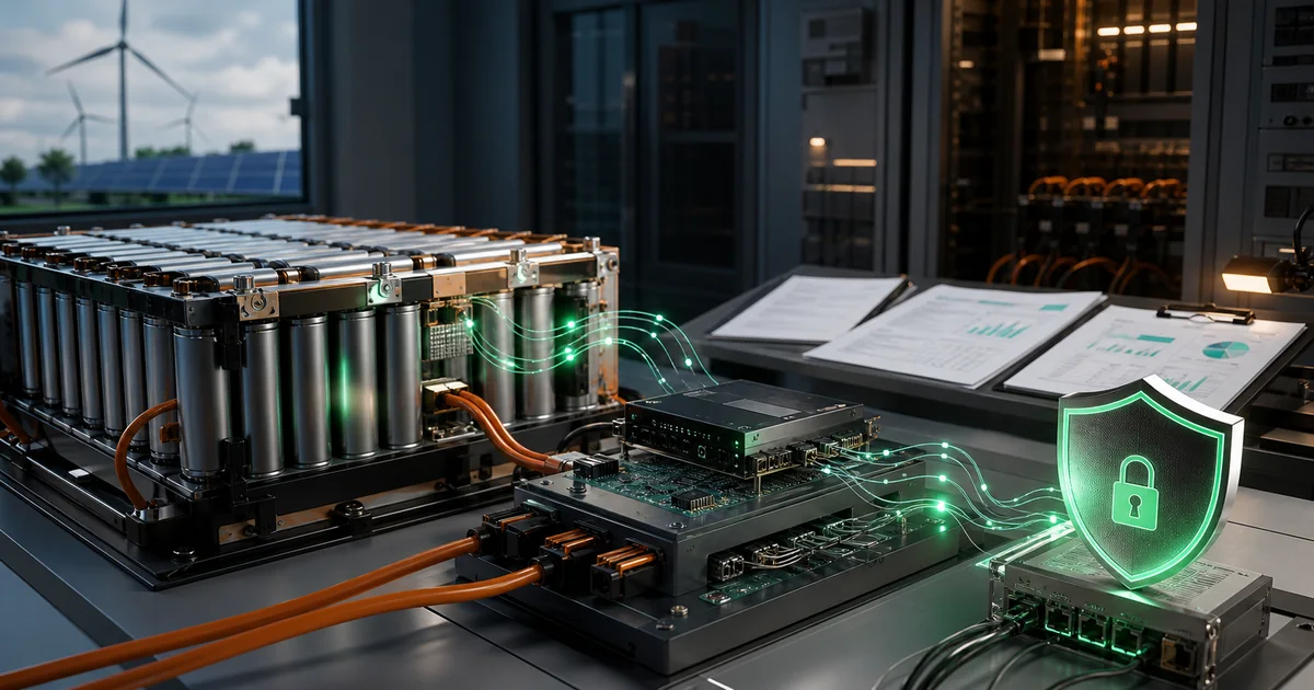
In the field of embedded software development, especially for applications such as home appliances, battery management systems (BMS), and energy storage systems (ESS), IEC 60730-1 Annex H is an indispensable functional safety standard. Based on the importance of control functions to safety, the standard classifies software control functions into three levels: Class A, Class B, and Class C.
Understanding the differences and requirements of these three categories is crucial for developing embedded systems that comply with functional safety standards. This article will provide an in-depth analysis of the definitions, software structure requirements, fault detection techniques for each category, and how to correctly select and implement them in actual projects.
★ Insight ─────────────────────────────────────
- Class Classification is the Result of Risk Assessment: Not all software functions require the same safety level. Classifying based on the severity of fault consequences is a core concept of functional safety.
- Table H.2 is the Implementation Guide: Table H.2 of IEC 60730-1 Annex H details acceptable measures for different hardware component faults, serving as a direct reference for engineering implementation.
- Standard Version Selection: IEC 60730-1:2022 is the current latest version, and UL 60730-1:2024 is the US nationally adopted version. Both are highly consistent in Annex H content. ─────────────────────────────────────────────────
1. Background of Class Classification System
1.1 Difference Between Functional Safety and Product Safety
Before diving into Class classification, it’s important to understand the difference between functional safety and traditional product safety:
| Comparison Dimension | Product Safety | Functional Safety |
|---|---|---|
| Implementation | Through physical means such as design, materials, structure, insulation | Through safety-related control functions and software logic |
| Focus | Preventing hazards during normal use (electric shock, fire, etc.) | Preventing hazards caused by control system faults |
| Typical Measures | Clearance, creepage distance, enclosure protection, flame retardant materials | Watchdog, CRC checksum, redundant design, fault detection |
| Assessment Standards | IEC 60335, IEC 60950, etc. | IEC 61508, IEC 60730 Annex H, etc. |
| Time Dimension | Static safety design | Dynamic fault response |
Functional safety focuses on system behavior when faults occur, ensuring that even with hardware or software faults, the system can enter or maintain a safe state. This is the core purpose of IEC 60730 Annex H Class classification.
1.2 IEC 60730-1 Standard Positioning
IEC 60730-1 is titled “Automatic electrical controls for household and similar use - Part 1: General requirements,” and its Annex H specifically specifies functional safety-related requirements.
This standard applies to:
- Household appliance controllers (refrigerators, washing machines, air conditioners, etc.)
- Automatic controllers for temperature, pressure, timers, etc.
- Battery Management Systems (BMS) - Required by various safety standards
- Energy storage system controllers
1.3 Standard Version Relationships
| Standard | Version | Release Date | Relationship |
|---|---|---|---|
| IEC 60730-1 | Edition 6 | September 2022 | International version |
| UL 60730-1 | Edition 6 | October 2024 | US nationally adopted version |
| IEC 61508 | Edition 2 | 2010 | Functional safety base standard |
Important Note: UL 60730-1 Edition 6 is based on IEC 60730-1 Edition 6, with highly consistent Annex H content to the IEC version, with almost no substantive technical differences.
2. Class A - Basic Software Requirements
2.1 Definition and Characteristics
Class A Control Function Definition (H.3.21.1):
“control functions which are not intended to be relied upon for the safety of the application”
Control functions not relied upon for equipment safety
Core Characteristics:
- Faults do not result in safety risks
- No functional safety measures required
- Not subject to Annex H software structure requirements
2.2 Typical Application Scenarios
| Application Scenario | Function Example | Description |
|---|---|---|
| Appliance Control | Indoor temperature regulation | General temperature control, non-safety-related |
| User Interface | Display functions, status indication | Faults do not affect safety |
| Convenience Features | Timer functions, mode selection | Only affects user experience |
| BMS Applications | SOC calculation, battery level display | Non-safety-related functions |
2.3 Software Development Requirements
Class A functions do not need to meet the special requirements of Annex H, but should still follow basic software engineering practices:
- Basic coding standards
- Normal functional testing
- No fault detection mechanism requirements
3. Class B - Structured Safety Requirements (Key Focus)
3.1 Definition and Core Requirements
Class B Control Function Definition (H.3.21.2):
“control functions which are intended to prevent an unsafe state of the appliance”
Control functions intended to prevent the appliance from entering an unsafe state
Key Characteristics:
- Faults do not directly cause hazards (explicitly stated in standard notes)
- Must reach a safe state under single fault conditions
- Requires fault detection mechanisms
- If software is used, must meet Annex H requirements
3.2 Typical Class B Applications
3.2.1 Battery Management Systems (BMS)
| Function | Class B Classification | Detection Technique |
|---|---|---|
| Overcharge Protection | Class B | Voltage monitoring, program flow monitoring, watchdog |
| Over-temperature Protection | Class B | Temperature sensor redundancy, reasonableness check |
| Overcurrent Protection | Class B | Shunt monitoring, Hall sensor verification |
| SOC Calculation | Class A | (Non-safety-related) |
3.2.2 Other Applications
| Application Scenario | Safety Function | Control Category |
|---|---|---|
| Water Heater | Over-temperature protection (prevent water overheating) | Class B |
| Air Conditioning System | Compressor overload protection | Class B |
| Motor Control | Overcurrent protection | Class B |
| Pressure Vessel | Pressure limiter | Class B |
3.3 Class B Software Structure Requirements
According to IEC 60730-1 H.9.12.1.2.2, Class B control functions must adopt one of the following structures:
3.3.1 Single Channel + Functional Test (H.3.16.5)
┌─────────────────────────────────────┐
│         Single Processing Channel    │
│  ┌───────────────────────────────┐  │
│  │   CPU + Program Memory + Data  │  │
│  │        Memory                  │  │
│  └───────────────────────────────┘  │
└─────────────────────────────────────┘
              ↓
    ┌─────────────────┐
    │  Functional Test │
    │  (Startup Test)  │
└─────────────────┘Characteristics:
- Testing only at startup
- Suitable for applications with less strict fault detection time requirements
- Lowest cost
3.3.2 Single Channel + Periodic Self-Test (H.3.16.6) - Class B Minimum Requirement
┌─────────────────────────────────────┐
│         Single Processing Channel    │
│  ┌───────────────────────────────┐  │
│  │   CPU + Program Memory + Data  │  │
│  │        Memory                  │  │
│  └───────────────────────────────┘  │
└─────────────────────────────────────┘
              ↓
    ┌─────────────────┐
    │ Periodic Self-Test│
    │ (Runtime periodic)│
    │  - ROM CRC        │
    │  - RAM Test       │
    │  - Clock Monitor  │
└─────────────────┘Characteristics:
- Periodic detection during runtime
- Fault detection time can be controlled within a certain range
- Requires proper planning of test timing
3.3.3 Dual Channel Without Comparison (H.3.16.1)
┌─────────────┐     ┌─────────────┐
│  Channel A  │     │  Channel B  │
│  (Primary)  │     │  (Backup)   │
└─────────────┘     └─────────────┘
       ↓                   ↓
       └─────────┬─────────┘
                 ↓
         ┌───────────────┐
         │ Output Select │
         │     Logic     │
└───────────────┘Characteristics:
- Two independent channels
- No comparator required
- Typically used for voting or redundancy scenarios
3.4 Class B Fault Detection Techniques (Table H.2)
Table H.2 is the core content of Annex H, specifying acceptable measures for different component faults:
3.4.1 CPU Testing
Test Purpose: Detect faults within the processor to ensure correct instruction execution.
Acceptable Measures:
- Static memory test
- Single-bit redundant word protection
Test Method Example:
// CPU Register Test Pattern
#define TEST_PATTERN_1 0xAAAAAAAA
#define TEST_PATTERN_2 0x55555555
#define TEST_PATTERN_3 0xFFFFFFFF
#define TEST_PATTERN_4 0x00000000

bool TestCPURegisters(void) {
    volatile uint32_t reg;
    uint32_t backup;

    // Backup original value
    backup = reg;

    // Write and verify test pattern
    reg = TEST_PATTERN_1;
    if(reg != TEST_PATTERN_1) return false;

    reg = TEST_PATTERN_2;
    if(reg != TEST_PATTERN_2) return false;

    // ... Other pattern tests

    // Restore original value
    reg = backup;
    return true;
}
3.4.2 Program Memory Testing
Test Purpose: Ensure program code integrity, detect single-bit faults in Flash/ROM.
Class B Acceptable Measures:
- Periodically modified checksum
- Multiple checksum
- Single-bit redundant word protection
CRC-16 Check Implementation Example:
uint16_t CRC16_CCITT(const uint8_t* data, uint32_t length) {
    uint16_t crc = 0xFFFF;
    const uint16_t poly = 0x1021;

    for(uint32_t i = 0; i < length; i++) {
        crc ^= (uint16_t)data[i] << 8;
        for(uint8_t bit = 0; bit < 8; bit++) {
            if(crc & 0x8000) {
                crc = (crc << 1) ^ poly;
            } else {
                crc <<= 1;
            }
        }
    }
    return crc;
}

// Periodic CRC check
void PeriodicCRCCheck(void) {
    uint16_t calculated = CRC16_CCITT(FLASH_START_ADDR, FLASH_SIZE);
    uint16_t stored = GetStoredCRC();

    if(calculated != stored) {
        EnterSafeState();  // Enter safe state
    }
}
3.4.3 Data Memory Testing
Test Purpose: Detect RAM stuck-at faults and dynamic coupling faults.
Class B Acceptable Measures:
- Periodic static memory test
- Single-bit redundant word protection
March Test Algorithm Example:
bool MarchTestRAM(uint8_t* start, uint32_t size) {
    // Write 0 upward
    for(uint32_t i = 0; i < size; i++) {
        start[i] = 0x00;
    }

    // Read/write 0xAA upward, then write 0x55
    for(uint32_t i = 0; i < size; i++) {
        if(start[i] != 0x00) return false;
        start[i] = 0xAA;
    }

    // Read/write 0x55 upward, then write 0x00
    for(uint32_t i = 0; i < size; i++) {
        if(start[i] != 0xAA) return false;
        start[i] = 0x55;
    }

    // ... Continue reverse testing

    return true;
}
3.4.4 Clock Testing
Test Purpose: Detect clock frequency anomalies (too high or too low).
Class B Acceptable Measures:
- Frequency monitoring - Comparison with independent fixed frequency
- Time slot monitoring (watchdog)
Frequency Monitoring Implementation Example:
bool MonitorClockFrequency(void) {
    static uint32_t last_count = 0;
    uint32_t current_count = GetTimerCounter();
    uint32_t delta = current_count - last_count;
    last_count = current_count;

    // Calculate percentage deviation
    int32_t error = (int32_t)delta - (int32_t)EXPECTED_FREQ_COUNT;
    int32_t error_percent = (error * 100) / EXPECTED_FREQ_COUNT;

    if(abs(error_percent) > TOLERANCE_PERCENT) {
        return false;  // Clock frequency anomaly
    }
    return true;
}
3.4.5 Program Flow Monitoring
Monitoring Principle: Detect program flow anomalies by monitoring the logic and timing of program execution.
Acceptable Measures:
- Periodic self-test
- Independent time slot monitoring
- Logic monitoring
Logic Monitoring Implementation Example:
typedef enum {
    PHASE_INIT = 0,
    PHASE_INPUT_READ,
    PHASE_CONTROL_CALC,
    PHASE_OUTPUT_WRITE,
    PHASE_DIAGNOSTIC,
} Phase_t;

static Phase_t current_phase = PHASE_INIT;
static Phase_t expected_next_phase = PHASE_INPUT_READ;

void CheckProgramFlow(void) {
    if(current_phase != expected_next_phase) {
        EnterSafeState();  // Program flow anomaly
    }

    // Set next expected phase
    switch(current_phase) {
        case PHASE_INIT:
            expected_next_phase = PHASE_INPUT_READ;
            break;
        case PHASE_INPUT_READ:
            expected_next_phase = PHASE_CONTROL_CALC;
            break;
        // ... Other state transitions
    }
}
3.4.6 Watchdog Timer
Type Selection:
| Type | Characteristics | Applicable Scenario |
|---|---|---|
| Window Watchdog | Must feed within time window | Detect program running too fast or too slow |
| Timeout Watchdog | Only detects timeout | Basic monitoring |
| Independent Watchdog | Independent clock source | High reliability requirements |
Configuration Requirements: According to H.13.2.1.1, if using time slot monitoring, must be sensitive to both upper and lower limits.
Window Watchdog Configuration Example:
#define WDT_MIN_FEED_TIME_MS  9
#define WDT_MAX_FEED_TIME_MS  11

void FeedWindowWatchdog(void) {
    uint32_t current_time = GetSystemTimeMs();
    uint32_t elapsed = current_time - wwdt.last_feed_time;

    // Check if within window
    if(elapsed < WDT_MIN_FEED_TIME_MS) {
        // Feeding too early, possible program flow anomaly
        RecordError(ERROR_WDT_EARLY_FEED);
        while(1);  // Wait for watchdog timeout reset
    }

    if(elapsed > WDT_MAX_FEED_TIME_MS) {
        return;  // Feeding too late, watchdog already triggered
    }

    // Feed watchdog
    WDT->FEED = 0xAA;
    WDT->FEED = 0x55;
}
4. Class C - High Safety Level Requirements
4.1 Definition and Characteristics
Class C Control Function Definition (H.3.21.3):
“control functions which are intended to prevent special hazards such as explosion or whose failure could directly cause a hazard in the appliance”
Control functions intended to prevent special hazards (such as explosion) or whose failure could directly cause a hazard in the appliance
Key Characteristics:
- Prevent special hazards (such as explosion)
- Faults may directly cause hazards (Key difference from Class B)
- Requires higher levels of redundancy and monitoring
- Considers both first and second fault conditions
4.2 Typical Application Scenarios
| Application Scenario | Safety Function | Description |
|---|---|---|
| Burner Control System | Flame monitoring, gas shutoff | Failure may cause explosion |
| Enclosed Water System | Thermal cutoff | No exhaust protection, overpressure may cause explosion |
| Explosion-proof Related Control | Flammable environment monitoring | Directly involves explosion-proof safety |
Note: BMS in Energy Storage Systems (ESS) typically does not require Class C, Class B is sufficient to meet most safety requirements.
4.3 Class C Software Structure Requirements
According to IEC 60730-1 H.9.12.1.2.1, Class C control functions must adopt one of the following structures:
4.3.1 Single Channel + Periodic Self-Test + Monitoring (H.3.16.7)
┌─────────────────────────────────────────────┐
│   Single Channel + Self-Test + Monitor Arch │
├─────────────────────────────────────────────┤
│   ┌─────────┐    ┌─────────┐                │
│   │   CPU   │───→│ Memory  │                │
│   └────┬────┘    └─────────┘                │
│        │                                     │
│        │ Periodic Self-Test                  │
│        ↓                                     │
│   ┌─────────┐                               │
│   │ Self-Test│                               │
│   │ Program  │                               │
│   └────┬────┘                               │
│        │                                     │
│        ├──────────┐                          │
│        ↓          ↓                          │
│   ┌─────────┐ ┌─────────┐                   │
│   │Watchdog │ │Program  │                   │
│   │ Timer   │ │ Flow    │                   │
│   │(Time)   │ │ Monitor │                   │
│   └─────────┘ └─────────┘                   │
└─────────────────────────────────────────────┘
4.3.2 Dual Channel Homogeneous Comparison (H.3.16.3)
┌─────────────┐     ┌─────────────┐
│  Channel A  │     │  Channel B  │
│ (Homogeneous)│    │ (Homogeneous)│
└─────────────┘     └─────────────┘
       ↓                   ↓
       └─────────┬─────────┘
                 ↓
         ┌───────────────┐
         │   Comparator  │
         │ (Output Comp.)│
         └───────────────┘
4.3.3 Dual Channel Heterogeneous Comparison (H.3.16.2)
┌─────────────┐     ┌─────────────┐
│  Channel A  │     │  Channel B  │
│ (Design A)  │     │ (Design B)  │
└─────────────┘     └─────────────┘
       ↓                   ↓
       └─────────┬─────────┘
                 ↓
         ┌───────────────┐
         │   Comparator  │
         │ (Output Comp.)│
         └───────────────┘
Advantage of Heterogeneous Design: Can detect systematic design errors, as both channels use different designs to implement the same function.
5. Class Selection Decision Tree
5.1 Classification Decision Process
                    ┌─────────────────┐
                    │ Control Function│
                    │    Assessment   │
                    └────────┬────────┘
                             │
                    ┌────────▼────────┐
                    │ Does fault cause│
                    │ direct hazard?  │
                    └────┬───────┬────┘
                         │       │
                   Yes    │       │  No
                         │       │
                ┌────────▼───┐  ┌▼─────────────┐
                │  Class C   │  │ Function used│
                │ (prevent   │  │ to prevent   │
                │ explosion) │  │ unsafe state?│
                └────────────┘  └────┬────┬────┘
                                      │    │
                                Yes    │    │  No
                                      │    │
                             ┌────────▼─┐ ┌▼──────────┐
                             │  Class B │ │  Class A  │
                             │ (prevent │ │ (not relied│
                             │  unsafe) │ │  for safe)│
                             └──────────┘ └───────────┘
5.2 Decision Checklist
| Question | Yes → Class C | Yes → Class B | No → Class A |
|---|---|---|---|
| Can faults directly cause hazards (e.g., explosion)? | ✓ | ||
| Is it used to prevent special hazards (e.g., explosion-proof)? | ✓ | ||
| Is the function used to prevent unsafe states? | ✓ | ||
| Is this a safety-related protection function? | ✓ | ||
| Do faults affect safety? | ✓ |
5.3 Typical Function Classification Quick Reference
| Function | Class A | Class B | Class C |
|---|---|---|---|
| Temperature Display | ✓ | ||
| SOC Calculation | ✓ | ||
| Over-temperature Protection | ✓ | ||
| Over/Under Voltage Protection | ✓ | ||
| Overcurrent Protection | ✓ | ||
| Burner Control | ✓ | ||
| Explosion-proof Control | ✓ |
6. Comparison with UL 60730
6.1 Standard Relationship
UL 60730-1 is the US nationally adopted version of IEC 60730-1. The relationship between Edition 6 of both is as follows:
| Standard | Version | Release Date | Relationship |
|---|---|---|---|
| IEC 60730-1 | Edition 6 | September 2022 | International version |
| UL 60730-1 | Edition 6 | October 2024 | US nationally adopted version |
6.2 Annex H Comparison Conclusion
After detailed comparative analysis, IEC 60730-1 Annex H and UL 60730-1 Annex H are highly consistent in functional safety assessment requirements:
| Comparison Item | Conclusion |
|---|---|
| Terminology Definitions (H.3) | Completely consistent |
| Class A/B/C Classification | Completely consistent |
| Software Structure Requirements | Completely consistent |
| Table H.2 Fault Control Measures | Completely consistent |
| Software Lifecycle V Model | Completely consistent |
| Fault Assessment Requirements | Completely consistent |
| EMC Test Requirements | Completely consistent |
| Remote Control Encryption Requirements | Completely consistent |
6.3 Practical Recommendations
| Scenario | Recommendation |
|---|---|
| During certification assessment | Can use IEC 60730-1 Annex H for assessment, results applicable to UL certification |
| During documentation | No need to distinguish between IEC and UL functional safety requirements |
| During testing | Test methods and level standards are completely consistent |
| Focus area | Should focus on US national differences in other clauses, not Annex H |
7. Implementation Recommendations
7.1 Class B Implementation Roadmap
Phase 1: System Design Phase
├── Functional safety requirements analysis
├── Class function classification
├── Software architecture design
└── Fault detection time determination

Phase 2: Software Development Phase
├── Establish coding standards (MISRA C recommended)
├── Implement detection measures required by Table H.2
│   ├── CPU testing
│   ├── Memory testing
│   ├── Clock monitoring
│   └── Program flow monitoring
└── Unit testing

Phase 3: Integration Verification Phase
├── Integration testing
├── Fault injection testing
├── EMC testing (Level 3)
└── Documentation

Phase 4: Certification Preparation
├── Prepare documents required by Table H.1
├── Prepare assessment report
└── Third-party assessment
7.2 Key Documentation Requirements (Table H.1)
| Document | Description | Clause |
|---|---|---|
| Software Safety Requirements Specification | Define safety function requirements | H.8.1 |
| Software Architecture Design | Module division, data flow, control flow | H.8.2 |
| Fault Detection Time Declaration | Table H.1 Item H.8 | H.9.12.2.6 |
| Fault Response Declaration | Table H.1 Item H.9 | H.9.12.2.7 |
| Defined State Declaration | Table H.1 Item H.10 | H.3.22 |
| Software Verification Report | Unit/Integration test reports | H.9.12.3.3 |
7.3 Common Misconceptions
| Misconception | Correct Understanding |
|---|---|
| Class B requires dual-channel hardware | Class B can use single channel + periodic self-test |
| Watchdog is sufficient | Also need other detection measures specified in Table H.2 |
| Testing only at startup is enough | Class B requires periodic self-tests |
| Class C is always better than Class B | Choose appropriate level based on risk, over-design is not economical |
| IEC and UL standards are very different | Annex H content is highly consistent |
7.4 Recommended Tools and Resources
| Tool Type | Recommendation | Description |
|---|---|---|
| Coding Standard | MISRA C:2012 | Widely adopted in automotive industry, applicable to Class B |
| Static Analysis | Coverity, PC-lint | Code quality checking |
| Unit Testing Framework | Unity, CppUTest | Embedded C testing framework |
| Fault Injection | Software fault injection tools | Verify fault detection mechanisms |
Conclusion
The Class A/B/C classification system of IEC 60730-1 Annex H provides a clear framework for the safety design of embedded software. Understanding the differences, requirements, and implementation methods of these three categories is the foundation for developing systems that comply with functional safety standards.
Core Key Points Review:
- Class A: Control functions not relied upon for safety, no special requirements
- Class B: Prevent unsafe states, typical classification for BMS and other applications
- Class C: Prevent special hazards such as explosion, requires higher levels of redundancy
Implementation Keys:
- Correctly classify functions
- Meet fault detection requirements of Table H.2
- Follow software safety lifecycle V model
- Prepare complete documentation evidence
For most household appliance and energy storage system applications, Class B is the appropriate choice, meeting safety requirements while providing reasonable cost-effectiveness.
References
- IEC 60730-1:2022 - Automatic electrical controls - Part 1: General requirements
- UL 60730-1:2024 - Standard for Automatic Electrical Controls
- IEC 61508-3 - Functional safety of electrical/electronic/programmable electronic safety-related systems
- MISRA C:2012 - Guidelines for the use of the C language in critical systems
- IEC 62619:2017 - Safety requirements for secondary lithium cells and batteries
Publication Date: March 14, 2026 Version: 1.0