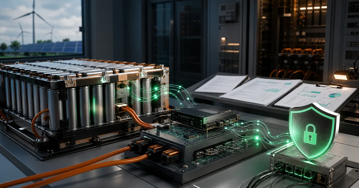
IEC 60730 Application Case Study in Energy Storage Systems
With the accelerating global energy transition, Energy Storage Systems (ESS) play an increasingly important role in power systems. From residential storage to grid-scale storage, the Battery Management System (BMS) serves as the “brain” of the energy storage system, and its functional safety reliability directly impacts the safe operation of the entire system.
IEC 60730-1 Annex H, as the core standard for functional safety of household controllers, provides a systematic methodology for safety design of software-controlled products like BMS. This article will use a practical residential energy storage BMS project as an example to demonstrate the complete application process of Class B requirements in energy storage systems.
★ Insight ─────────────────────────────────────
Triple Challenges in Energy Storage BMS Functional Safety
- Urgent fault detection time: Battery thermal runaway can occur within seconds, requiring fault detection and response times far lower than traditional appliances
- Hardware-software coordination complexity: Multiple protection functions require precise coordination between MCU, AFE, and power devices; failure of a single component can trigger chain reactions
- Standard applicability definition: Energy storage systems fall between household appliances and industrial equipment, requiring careful assessment of IEC 60730 applicability boundaries
─────────────────────────────────────────────────
1. BMS Functional Safety Requirements Background
1.1 Energy Storage System Safety Risk Analysis
Modern lithium battery energy storage systems face multiple safety risks that must be systematically controlled in BMS design:
| Risk Type | Trigger Condition | Potential Consequences | Fault Tolerance Time |
|---|---|---|---|
| Overvoltage Charging | Charging management failure, BMS misjudgment | Battery lithium plating, internal short circuit, thermal runaway | < 1 second |
| Undervoltage Discharge | Over-discharge protection failure | Permanent battery capacity loss, copper plating | < 5 seconds |
| Over-temperature | Cooling failure, high ambient temperature | Thermal runaway, fire, explosion | < 5 seconds |
| Overcurrent | Short circuit, abnormal load | Wire melting, equipment damage | < 100 ms |
| SOC Estimation Error | Algorithm defects | Non-safety related (Class A) | N/A |
Thermal runaway time window is the key constraint for functional safety design in energy storage systems. According to experimental data, the time window for lithium batteries from over-temperature trigger to thermal runaway onset is typically between 30-120 seconds. This means the BMS fault detection and response mechanism must reliably operate within this time window.
1.2 IEC 60730 Applicability Assessment
Before applying IEC 60730-1 Annex H to energy storage BMS, an applicability assessment is required:
flowchart TD
    A[Assess IEC 60730 Applicability] --> B{Product Application Scenario}
    B -->|Residential Storage| C[Apply IEC 60730]
    B -->|Grid-scale Storage| D[Reference IEC 61508]

    C --> E{Standard Combination Assessment}
    E --> F[IEC 60730-1<br/>Functional Safety]
    E --> G[IEC 62619<br/>Battery Safety]
    E --> H[IEC 62368-1<br/>AV Equipment Safety]

    F --> I[Class B Requirements<br/>Prevent Unsafe States]
    I --> J[Single Fault Tolerance<br/>Reach Safe State<br/>Within Fault Tolerance Time]

    style C fill:#e1f5ff
    style F fill:#ffe1e1
    style I fill:#fff4e1
Applicability Conclusion: For residential energy storage systems (typically rated voltage below 48V, power 5-15kW), IEC 60730-1 Annex H is an appropriate functional safety standard. Mainly based on the following reasons:
- Product attributes: Residential storage falls within the scope of “household and similar electrical appliances”
- Control method: BMS is centered on electronic controllers with primarily software control
- Risk level: Class B is sufficient to cover the safety risks of energy storage systems
- Market access: IEC 60730 certification facilitates entry into European and American markets
1.3 Safety Function Classification Matrix
According to IEC 60730-1 H.3.21 definition, classify BMS functions:
| Function Module | Specific Function | Class Classification | Classification Basis | Standard Clause |
|---|---|---|---|---|
| Voltage Protection | Overcharge protection | Class B | Prevent unsafe states caused by battery overvoltage | H.3.21.2 |
| Undervoltage protection | Class B | Prevent unsafe states caused by battery undervoltage | H.3.21.2 | |
| Temperature Protection | Over-temperature protection | Class B | Prevent thermal runaway caused by battery over-temperature | H.3.21.2 |
| Low-temperature protection | Class B | Prevent battery damage from low-temperature charging | H.3.21.2 | |
| Current Protection | Overcurrent protection | Class B | Prevent equipment damage caused by overcurrent | H.3.21.2 |
| Short circuit protection | Class B | Quickly cut off short circuit current | H.3.21.2 | |
| State Estimation | SOC calculation | Class A | Does not affect safety, status indication only | H.3.21.1 |
| SOH calculation | Class A | Does not affect safety, status indication only | H.3.21.1 | |
| Communication | BMS communication | Class A | Non-safety critical data transmission | H.3.21.1 |
Key distinction principle: The judgment basis is “whether the fault directly leads to dangerous situations.” Class B function faults themselves do not directly cause danger but may lead to unsafe states; while Class C function faults may directly lead to danger. Most energy storage BMS functions fall within the Class B category.
2. Applicability of IEC 60730 in BMS
2.1 Class B Software Structure Selection
IEC 60730-1 H.9.12.1.2.2 provides three Class B software structure options. For BMS applications, we recommend the single-channel + periodic self-test + monitoring architecture:
┌─────────────────────────────────────────────────────────────┐
│                  BMS Class B Software Architecture            │
├─────────────────────────────────────────────────────────────┤
│                                                             │
│   ┌──────────────────────────────────────────────────┐      │
│   │              Application Layer                     │      │
│   │  ┌─────────┐  ┌─────────┐  ┌─────────┐          │      │
│   │  │SOC Calc │  │Charge/  │  │Comm.    │ Class A │      │
│   │  │         │  │Discharge│  │Mgmt.    │          │      │
│   │  └─────────┘  └─────────┘  └─────────┘          │      │
│   └──────────────────────────────────────────────────┘      │
│                           ↓                                  │
│   ┌──────────────────────────────────────────────────┐      │
│   │            Safety Protection Layer                 │      │
│   │  ┌─────────┐  ┌─────────┐  ┌─────────┐          │      │
│   │  │Overvolt. │  │Overtemp.│  │Overcurr.│ Class B │      │
│   │  │Protect. │  │Protect. │  │Protect. │          │      │
│   │  └─────────┘  └─────────┘  └─────────┘          │      │
│   └──────────────────────────────────────────────────┘      │
│                           ↓                                  │
│   ┌──────────────────────────────────────────────────┐      │
│   │             Monitoring Layer                       │      │
│   │  ┌─────────┐  ┌─────────┐  ┌─────────┐          │      │
│   │  │Watchdog │  │Program  │  │Clock    │  Monitor │      │
│   │  │Timer    │  │Flow Mon.│  │Monitor  │          │      │
│   │  └─────────┘  └─────────┘  └─────────┘          │      │
│   └──────────────────────────────────────────────────┘      │
│                           ↓                                  │
│   ┌──────────────────────────────────────────────────┐      │
│   │           Self-test Layer                          │      │
│   │  ┌─────────┐  ┌─────────┐  ┌─────────┐          │      │
│   │  │Flash CRC│  │RAM Test │  │CPU Test │  Self-   │      │
│   │  │         │  │         │  │         │  test    │      │
│   │  └─────────┘  └─────────┘  └─────────┘          │      │
│   └──────────────────────────────────────────────────┘      │
│                           ↓                                  │
│   ┌──────────────────────────────────────────────────┐      │
│   │         Hardware Abstraction Layer                 │      │
│   │  ┌─────────┐  ┌─────────┐  ┌─────────┐          │      │
│   │  │ADC Driver│  │GPIO Driver│  │Comm.   │          │      │
│   │  │         │  │         │  │Driver   │          │      │
│   │  └─────────┘  └─────────┘  └─────────┘          │      │
│   └──────────────────────────────────────────────────┘      │
│                                                             │
└─────────────────────────────────────────────────────────────┘
Architecture design considerations:
- Layered isolation: Class A and Class B functions are clearly separated in the software architecture
- Independence: Monitoring layer is independent of application layer, can detect even if application layer is abnormal
- Periodicity: Self-test tasks execute at fixed periods to ensure runtime fault detection
- Priority: Safety-related tasks are assigned highest interrupt priority
2.2 Table H.2 Compliance Matrix
Table H.2 is the core of IEC 60730-1 Annex H, defining acceptable measures for different component faults. The following is the BMS compliance matrix:
| Component | Fault Mode | Class B Requirement | Implementation Measure | Detection Period | Response Method |
|---|---|---|---|---|---|
| CPU Registers | Stuck-at/DC | Functional test or periodic self-test | Startup register test + runtime periodic test | 24h | System reset |
| Program Counter | Stuck-at | Time period monitoring + logic monitoring | Window watchdog + state machine monitoring | 100ms | Safe state |
| Clock | Wrong frequency | Frequency monitoring | Internal RC vs external crystal comparison | 1s | Switch to safe clock |
| Flash | Single bit fault | CRC or checksum | CRC-16 startup verification | At startup | Prohibit operation |
| RAM | DC fault | Static memory test | March C algorithm block test | 1h | Safe state |
| ADC | Data error | Plausibility check | Range check + 2-out-of-3 logic | 10ms | Safe state |
| Communication Interface | Data error | Hamming distance 3 | CRC-16 verification | Per frame | Discard packet |
| Digital I/O | Wrong output | Plausibility check | Output readback verification | 100ms | Turn off output |
Key design decisions:
- Detection period allocation: Determine detection period based on fault tolerance time; overcurrent protection requires 100ms detection, while RAM testing can be extended to 1h
- Response strategy: Distinguish between “system reset” and “safe state” to ensure actuators like relays are in safe position
- Redundancy strategy: ADC uses 2-out-of-3 logic, communication uses CRC-16 to ensure Hamming distance ≥ 3
★ Insight ─────────────────────────────────────
Three Levels of Table H.2 Compliance
- Complete self-test at startup: Utilize system startup time window to perform complete testing of CPU, Flash, and RAM; this is the concrete embodiment of “functional test” requirements
- Runtime periodic self-test: Decompose long-duration tests into small tasks executed periodically, such as RAM block testing, balancing detection coverage with real-time performance
- Continuous monitoring mechanisms: Real-time monitoring methods such as watchdog and program flow monitoring constitute the first line of defense for fault detection
─────────────────────────────────────────────────
3. Typical BMS Safety Function Analysis
3.1 Overvoltage Protection Function Design
Overvoltage protection is one of the most core safety functions in BMS, and its design must meet Class B single fault tolerance requirements.
Hardware Architecture
┌─────────────────────────────────────────────────────────────┐
│                    Overvoltage Protection Hardware Architecture │
├─────────────────────────────────────────────────────────────┤
│                                                             │
│  Battery Pack ──→ Voltage Divider Network ──→ ADC1 ──→ ┌─────────┐ │
│              (Redundant sampling)    ↓            │         │ │
│                          ADC2 ───────→│  MCU    │ │
│                                       │ Class B │ │
│  Reference Voltage ──→ Hardware Comparator ───────→│  Logic  │ │
│  (Independent ref)    (Independent threshold)      │         │ │
│                          ↓            │         │ │
│  Software Judgment ─────────────────────→│         │ │
│                          ↓            │         │ │
│  Protection Logic ──────────────────────→│         │ │
│                                       └────┬────┘ │
│                                            ↓       │
│  ┌─────────┐         ┌─────────┐      ┌─────────┐│
│  │Relay 1  │←───────←│ Driver  │←─────│ GPIO Out││
│  │(Main    │         │Circuit  │      │(Redund.)││
│  │Protect.) │         │(Dual ch)│      │         ││
│  └─────────┘         └─────────┘      └─────────┘│
│                                                             │
└─────────────────────────────────────────────────────────────┘
Hardware design points:
- Dual ADC sampling: Two independent ADC channels collect voltage, achieving hardware redundancy
- Hardware comparator: Overvoltage detection independent of MCU, can operate even if MCU fails
- Dual relays: Main circuit dual relays in series, single relay stuck can still open circuit
- Driver circuit monitoring: Driver circuit has feedback detection to identify driver faults
Software Implementation
/**
 * @brief Overvoltage protection detection function (Class B)
 * @note Satisfies IEC 60730-1 Table H.2 requirements
 * @param voltage_1 ADC1 sampling value (mV)
 * @param voltage_2 ADC2 sampling value (mV)
 * @return uint8_t Protection action status
 */
uint8_t OverVoltage_Protection(uint16_t voltage_1, uint16_t voltage_2)
{
    static uint8_t error_count = 0;
    const uint16_t OV_THRESHOLD = 4200;  // 4.2V overvoltage threshold
    const uint16_t OV_RECOVERY = 4100;   // 4.1V recovery threshold
    const uint8_t ERROR_LIMIT = 3;       // Consecutive error count

    // Plausibility check: ADC value range verification
    if ((voltage_1 > 5000) || (voltage_1 < 2000) ||
        (voltage_2 > 5000) || (voltage_2 < 2000)) {
        // ADC value exceeds reasonable range, possible ADC fault
        error_count++;
        if (error_count >= ERROR_LIMIT) {
            Enter_Safe_State();
            return SAFETY_STATE_ADC_FAULT;
        }
        return SAFETY_STATE_NORMAL;
    }

    // Dual ADC comparison: Difference should not exceed 50mV
    if (abs(voltage_1 - voltage_2) > 50) {
        error_count++;
        if (error_count >= ERROR_LIMIT) {
            // ADC mismatch, possible single channel fault
            Enter_Safe_State();
            return SAFETY_STATE_ADC_MISMATCH;
        }
        return SAFETY_STATE_NORMAL;
    }

    // Average voltage values (after dual channel verification)
    uint16_t voltage_avg = (voltage_1 + voltage_2) / 2;

    // Overvoltage detection
    if (voltage_avg > OV_THRESHOLD) {
        ov_error_count++;
        if (ov_error_count >= ERROR_LIMIT) {
            // Consecutive overvoltage detected, trigger protection
            Relay_Turn_Off(RELAY_CHARGE);
            return SAFETY_STATE_OVERVOLTAGE;
        }
    } else if (voltage_avg < OV_RECOVERY) {
        // Voltage recovered, clear error count
        ov_error_count = 0;
    }

    error_count = 0;  // No error, clear count
    return SAFETY_STATE_NORMAL;
}
Software design points:
- Plausibility check: First verify ADC value is within reasonable range to prevent abnormal values from falsely triggering protection
- Dual channel comparison: Two ADC channel values should be close; excessive difference indicates possible single channel fault
- Consecutive error counting: Prevent false triggers from instantaneous interference; require N consecutive detections before action
- Hysteresis design: Separate protection threshold from recovery threshold to prevent repeated switching near threshold
3.2 Over-temperature Protection Function Design
Over-temperature protection faces special challenges from sensor faults, requiring more complex detection logic.
Sensor Layout Strategy
Battery Pack Temperature Sensor Layout
┌─────────────────────────────────────────────────────────────┐
│                                                             │
│  ┌──────┐    ┌──────┐    ┌──────┐    ┌──────┐              │
│  │Cell 1│    │Cell 2│    │Cell 3│    │Cell 4│    ...        │
│  │      │    │      │    │      │    │      │              │
│  │  NT1 │    │  NT2 │    │  NT3 │    │  NT4 │              │
│  └──────┘    └──────┘    └──────┘    └──────┘              │
│     │          │          │          │                     │
│     └──────────┴──────────┴──────────┘                    │
│                    │                                        │
│                    ↓                                        │
│            ┌───────────────┐                                │
│            │   Multiplexer │                                │
│            └───────┬───────┘                                │
│                    ↓                                        │
│            ┌───────────────┐                                │
│            │   ADC + MCU   │                                │
│            │   Class B     │                                │
│            └───────────────┘                                │
│                                                             │
│  Redundant design:                                          │
│  - At least 2 temperature sensors per battery module        │
│  - Sensors placed at different physical locations            │
│  - Single sensor fault does not affect overall protection   │
└─────────────────────────────────────────────────────────────┘
Sensor Fault Detection
/**
 * @brief Temperature sensor fault detection (Class B)
 * @note Detect open circuit, short circuit, drift faults
 * @param sensor_id Sensor ID
 * @param temp_adc ADC raw value
 * @return uint8_t Sensor status
 */
uint8_t Temp_Sensor_Check(uint8_t sensor_id, uint16_t temp_adc)
{
    const uint16_t ADC_MIN = 100;   // Corresponds to approximately 125°C (NTC 10k@25°C)
    const uint16_t ADC_MAX = 4000;  // Corresponds to approximately -40°C
    const uint16_t ADC_OPEN = 4090; // Open circuit characteristic value
    const uint16_t ADC_SHORT = 10;  // Short circuit characteristic value

    // Open circuit detection
    if (temp_adc > ADC_OPEN) {
        return TEMP_SENSOR_OPEN;
    }

    // Short circuit detection
    if (temp_adc < ADC_SHORT) {
        return TEMP_SENSOR_SHORT;
    }

    // Plausibility check: Exceeds physically possible range
    if ((temp_adc < ADC_MIN) || (temp_adc > ADC_MAX)) {
        return TEMP_SENSOR_OUT_OF_RANGE;
    }

    // Inter-sensor consistency check
    uint16_t temp_neighbor_1 = Get_Temperature(sensor_id - 1);
    uint16_t temp_neighbor_2 = Get_Temperature(sensor_id + 1);

    if ((temp_adc > temp_neighbor_1 + 200) &&
        (temp_adc > temp_neighbor_2 + 200)) {
        // Excessive temperature difference from adjacent sensors, possible drift
        return TEMP_SENSOR_DRIFT;
    }

    return TEMP_SENSOR_OK;
}
3.3 Overcurrent Protection Function Design
Overcurrent protection has the strictest response time requirement (< 100ms), requiring coordinated hardware and software design.
Hardware Overcurrent Detection
┌─────────────────────────────────────────────────────────────┐
│                   Overcurrent Protection Hardware Architecture │
├─────────────────────────────────────────────────────────────┤
│                                                             │
│  Current path:                                              │
│                                                             │
│  BATT+ ──→ [Shunt] ──→ [Load] ──→ BATT-                     │
│              │                                              │
│              ↓ (Differential signal)                        │
│         ┌─────────┐                                        │
│         │ Current │                                        │
│         │ Sense   │                                        │
│         │ Amplifier│                                        │
│         └────┬────┘                                        │
│              │                                             │
│              ├─────────→ ADC ──→ MCU (Software judgment)    │
│              │                                             │
│              ↓                                             │
│         ┌─────────┐                                        │
│         │Hardware │←─── Threshold setting (adjustable)      │
│         │Comparator│                                        │
│         └────┬────┘                                        │
│              │                                             │
│              ↓                                             │
│         ┌─────────┐      ┌──────────┐      ┌─────────┐    │
│         │Fast     │ ───→ │ Driver   │ ───→ │ MOSFET  │    │
│         │Latch    │      │ Circuit  │      │ (Turn   │    │
│         │Trigger  │      │ (High    │      │ off)    │    │
│         └─────────┘      speed)    │      └─────────┘    │
│                           └──────────┘                    │
│  Response time:                                             │
│  - Hardware path: < 10μs (comparator + latch + driver)     │
│  - Software path: < 100ms (ADC sampling + algorithm + action) │
│                                                             │
└─────────────────────────────────────────────────────────────┘
Design points:
- Hardware priority: Hardware comparator provides < 10μs response time as primary protection
- Software redundancy: Software provides secondary protection and more precise current measurement
- Latch mechanism: Hardware trigger requires MCU reset to recover, preventing repeated triggering
4. Class B Implementation Architecture
4.1 Software Architecture Design
BMS software meeting Class B requirements should use a layered architecture to ensure effective isolation and monitoring of safety functions.
Main Control Loop Design
/**
 * @brief BMS main control loop (Class B)
 * @note Satisfies IEC 60730-1 H.9.12 requirements
 */
void BMS_Main_Loop(void)
{
    static uint32_t loop_counter = 0;
    static uint32_t last_feed_time = 0;

    // System initialization
    BMS_System_Init();

    // Main loop
    while (1) {
        uint32_t loop_start = Get_System_Time_ms();

        // ========== Phase 1: Input sampling ==========
        current_phase = PHASE_INPUT_READ;
        Check_Program_Flow();  // Program flow monitoring

        Read_All_Voltages();   // Voltage sampling
        Read_All_Temperatures(); // Temperature sampling
        Read_Current();        // Current sampling

        // ========== Phase 2: Safety protection judgment ==========
        current_phase = PHASE_SAFETY_CHECK;
        Check_Program_Flow();

        // Class B safety functions
        OverVoltage_Protection();
        UnderVoltage_Protection();
        OverTemperature_Protection();
        OverCurrent_Protection();

        // Class A functions
        SOC_Estimation();
        SOH_Estimation();

        // ========== Phase 3: Control output ==========
        current_phase = PHASE_OUTPUT_WRITE;
        Check_Program_Flow();

        // Control relay status
        Update_Relay_Status();

        // ========== Phase 4: Periodic self-test ==========
        current_phase = PHASE_SELF_TEST;
        Check_Program_Flow();

        // Execute RAM test every 100 main loops
        if ((loop_counter % 100) == 0) {
            RAM_Test_Block(current_ram_block);
            current_ram_block = (current_ram_block + 1) % RAM_BLOCK_COUNT;
        }

        // Execute CPU test every 1000 main loops
        if ((loop_counter % 1000) == 0) {
            CPU_Test_Periodic();
        }

        // ========== Phase 5: Watchdog feed ==========
        current_phase = PHASE_WATCHDOG_FEED;
        Check_Program_Flow();

        // Check system health status
        if (System_Healthy_Check()) {
            // System normal, feed watchdog within time window
            uint32_t elapsed = Get_System_Time_ms() - last_feed_time;
            if ((elapsed >= WDT_MIN_FEED_TIME) &&
                (elapsed <= WDT_MAX_FEED_TIME)) {
                Watchdog_Feed();
                last_feed_time = Get_System_Time_ms();
            }
        } else {
            // System abnormal, don't feed watchdog, wait for watchdog reset
            __disable_irq();
            while (1);  // Wait for watchdog reset
        }

        loop_counter++;

        // Ensure loop time is within watchdog window
        uint32_t loop_time = Get_System_Time_ms() - loop_start;
        if (loop_time < WDT_MIN_FEED_TIME) {
            Delay(WDT_MIN_FEED_TIME - loop_time);
        }
    }
}
Design points:
- Phased execution: Divide main loop into clear phases for easy program flow monitoring
- Safety priority: Class B functions execute before Class A functions
- Periodic self-test: RAM and CPU tests are distributed across multiple loop cycles
- Watchdog management: Check system health status before feeding watchdog; actively trigger reset on abnormality
4.2 Clock Monitoring Implementation
The clock is the heart of the BMS system; clock failure can cause all timing functions to fail.
/**
 * @brief Clock monitoring implementation (Class B)
 * @note Satisfies IEC 60730-1 H.3.18.10.1 frequency monitoring requirements
 */
void Clock_Monitor_Init(void)
{
    // Use internal RC clock as reference
    RCC_OscInitTypeDef RCC_OscInitStruct = {0};
    RCC_OscInitStruct.OscillatorType = RCC_OSCILLATORTYPE_HSI;
    RCC_OscInitStruct.HSIState = RCC_HSI_ON;
    HAL_RCC_OscConfig(&RCC_OscInitStruct);

    // Configure timer to measure external crystal frequency
    // Use HSI as time base, measure HSE period
}

/**
 * @brief Periodic clock monitoring
 * @return true Clock normal, false Clock abnormal
 */
bool Clock_Monitor_Check(void)
{
    const uint32_t EXPECTED_COUNT = 1000;  // Expected count value
    const uint32_t TOLERANCE_PERCENT = 5;   // ±5% tolerance

    // Use HSI timer to measure HSE period
    uint32_t hse_count = Measure_HSE_Frequency();

    // Calculate percentage deviation
    int32_t error = (int32_t)hse_count - (int32_t)EXPECTED_COUNT;
    int32_t error_percent = (error * 100) / EXPECTED_COUNT;

    // Check if within tolerance
    if (abs(error_percent) > TOLERANCE_PERCENT) {
        // Clock abnormal, record error
        clock_error_count++;

        if (clock_error_count >= 3) {
            // Consecutive clock abnormalities detected
            // Switch to internal RC clock or enter safe state
            Enter_Safe_State();
            return false;
        }
    } else {
        clock_error_count = 0;
    }

    return true;
}
4.3 Watchdog Configuration
Window watchdog is the core monitoring mechanism for Class B systems.
/**
 * @brief Window watchdog configuration (Class B)
 * @note Satisfies IEC 60730-1 H.3.18.10.4 time period monitoring requirements
 */
void Window_Watchdog_Init(void)
{
    // Window watchdog parameters
    // Prescaler: 8
    // Counter value: 127
    // Window value: 80
    // Timeout time: Approximately 40ms (40MHz / 8 / 127)
    // Window lower limit: Approximately 20ms

    WWDG_HandleTypeDef hwwdg = {0};

    hwwdg.Instance = WWDG;
    hwwdg.Init.Prescaler = WWDG_PRESCALER_8;
    hwwdg.Init.Window = 80;      // Window lower limit value
    hwwdg.Init.Counter = 127;    // Counter reload value
    hwwdg.Init.EWIMode = WWDG_EWI_ENABLE;  // Enable early wakeup interrupt

    HAL_WWDG_Init(&hwwdg);
}

/**
 * @brief Watchdog feed function
 * @note Must be called within time window
 */
void Watchdog_Feed(void)
{
    uint32_t current_time = Get_System_Time_ms();
    static uint32_t last_feed_time = 0;
    uint32_t elapsed = current_time - last_feed_time;

    // Check if within time window
    if (elapsed < WDT_MIN_FEED_TIME) {
        // Feed too early, possible program flow abnormality
        Record_Error(ERROR_WDT_EARLY_FEED);
        while (1);  // Wait for watchdog reset
    }

    if (elapsed > WDT_MAX_FEED_TIME) {
        // Feed too late, watchdog already triggered
        return;
    }

    // Feed watchdog
    HAL_WWDG_Refresh(&hwwdg);
    last_feed_time = current_time;
}
5. Testing and Verification Points
5.1 Fault Injection Test Plan
Complete fault injection testing is key to verifying Class B compliance.
| Test Item | Fault Injection Method | Detection Method | Response Requirement | Record Number |
|---|---|---|---|---|
| Flash Fault | Modify Flash content | CRC detection | Prohibit operation at startup | TEST-FLASH-001 |
| RAM Fault | Write incorrect data | March test | Detect at startup | TEST-RAM-001 |
| Watchdog Test | Prevent feeding | Watchdog reset | Reset within 40ms | TEST-WDG-001 |
| Clock Fault | Switch to faulty clock source | Frequency monitoring | Detect within 1s | TEST-CLK-001 |
| ADC Fault | Inject incorrect voltage | Plausibility check | Detect within 100ms | TEST-ADC-001 |
| Communication Fault | Inject incorrect data | CRC verification | Discard error frame | TEST-COM-001 |
| Relay Stuck | Short relay contacts | Readback detection | Detect and alarm | TEST-RLY-001 |
5.2 EMC Test Requirements
According to IEC 60730-1 H.25, Class B protection control must meet at least test level 3:
| Test Item | Level 3 Requirements | BMS Application Characteristics |
|---|---|---|
| Voltage Dip/Interrupt | 100% dip 10 cycles | Ensure BMS does not malfunction during power fluctuations |
| Surge Immunity | 2kV line-line, 4kV line-ground | Charging port connected to grid, high surge risk |
| EFT/Burst | 2kV, 5kHz | Relay action generates interference |
| Electrostatic Discharge | Contact 4kV, Air 8kV | User operation panel |
| RF Radiation Immunity | 10V/m, 80-1000MHz | Communication equipment influence |
5.3 Temperature Test Verification
flowchart LR
    A[Temperature Test Plan] --> B[Low Temp Test<br/>-20°C]
    A --> C[Room Temp Test<br/>25°C]
    A --> D[High Temp Test<br/>60°C]

    B --> E[Verify: Sensor accuracy<br/>Protection function response]
    C --> E
    D --> E

    E --> F{Pass?}
    F -->|No| G[Adjust Design]
    F -->|Yes| H[Temperature Cycling Test<br/>-20°C ↔ 60°C]

    G --> E
    H --> I[Final Verification Report]

    style F fill:#fff4e1
    style I fill:#e1ffe1
6. Project Experience Summary
6.1 Common Non-compliance Analysis
Based on actual BMS assessment experience, the following are the most common non-compliances:
| NC Number | Problem Description | Standard Clause | Rectification Recommendation |
|---|---|---|---|
| NC-001 | Watchdog timeout too long (>1s) | H.3.18.10.4 | Adjust to 100ms based on strictest fault tolerance time |
| NC-002 | RAM only tested at startup | Table H.2 | Add runtime periodic block testing |
| NC-003 | Program flow monitoring missing | H.3.18.10.2 | Implement state machine monitoring and program signature |
| NC-004 | Clock not verified | H.3.18.10.1 | Add external crystal vs internal RC comparison verification |
| NC-005 | Temperature sensor has no fault detection | H.3.18.13 | Add open circuit, short circuit, drift detection |
| NC-006 | EMC test level insufficient | H.25 | Re-test at level 3 |
6.2 Best Practice Recommendations
Design phase:
- Early involvement: Introduce functional safety requirements at concept design stage
- Architecture first: Choose appropriate software architecture to avoid large-scale later refactoring
- Documentation first: Write software architecture documents and requirement specifications in a timely manner
Implementation phase:
- Incremental verification: Perform unit testing immediately after each module is completed
- Code review: Safety-related code must undergo peer review
- Static analysis: Use coding standard checking tools like MISRA C
Verification phase:
- Full coverage testing: Ensure each fault in Table H.2 has a corresponding test
- Physical verification: Fault injection must be performed on actual hardware, not rely on simulation alone
- EMC focus: EMC testing is often the most easily overlooked aspect
6.3 Cost-Benefit Analysis
| Project Class B Measure | Development Cost Increase | Certification Cost | Market Value |
|---|---|---|---|
| Software architecture optimization | +15-20% | - | Improve product reliability |
| Watchdog configuration | +1% | - | Basic requirement |
| Memory protection | +5% | - | Prevent software anomalies |
| Fault injection testing | +10% | - | Verify design effectiveness |
| Documentation preparation | +10% | Certification fee: 50-100k | Market access essential |
| EMC testing | - | Testing fee: 20-50k | Regulatory requirement |
Overall assessment: For energy storage BMS products targeting international markets, the input-output ratio of Class B compliance work is reasonable. Development cost increase is approximately 20-30%, but can achieve:
- Market access qualifications (IEC/CE/UL, etc.)
- Improved product reliability
- Enhanced brand reputation
- Reduced liability risk
★ Insight ─────────────────────────────────────
Strategic Value of Class B Certification
- Market access threshold: Functional safety requirements for energy storage products in European and American markets are becoming increasingly strict; Class B certification has changed from a “bonus” to a “necessity”
- Liability risk avoidance: Complete functional safety documentation system can serve as a basis for liability determination in case of accidents, reducing legal risk
- Technical accumulation: Technical specifications and testing capabilities established during Class B development process can be reused in other product lines
─────────────────────────────────────────────────
Conclusion
IEC 60730-1 Annex H Class B requirements provide a systematic methodology for functional safety design of energy storage BMS. Through this case study, we can see:
- Standard applicability: IEC 60730 applies to residential energy storage systems, Class B level is sufficient to cover major safety risks
- Importance of architecture: Reasonable hardware and software architecture is the foundation for meeting Class B requirements
- Necessity of verification: Complete fault injection testing and EMC testing are key to verifying compliance
- Documentation support: Complete documentation system is the prerequisite for assessment and certification
For BMS development engineers and energy storage product managers, understanding and applying IEC 60730 requirements is not only a certification need, but also a strategic investment to improve product reliability and market competitiveness.
Functional safety is a continuous improvement process. Class B compliance work lays a solid foundation for full lifecycle safety management of products. With the rapid development of the energy storage industry, functional safety standard applications will become increasingly widespread. We hope this case analysis provides valuable reference for industry colleagues.
Reference Standards
| Standard Number | Standard Name | Version |
|---|---|---|
| IEC 60730-1 | Automatic electrical controls for household and similar use - Part 1: General requirements | 2022 |
| IEC 62619 | Safety requirements for secondary lithium cells and batteries for use in electrical energy storage systems | 2022 |
| IEC 62368-1 | Audio/video, information and communication technology equipment - Part 1: Safety requirements | 2018 |
| IEC 61000-4-2 | Electromagnetic compatibility (EMC) - Testing and measurement techniques - Electrostatic discharge immunity test | 2008 |
| IEC 61000-4-3 | Electromagnetic compatibility (EMC) - Testing and measurement techniques - Radiated, radio-frequency, electromagnetic field immunity test | 2006 |
| IEC 61000-4-4 | Electromagnetic compatibility (EMC) - Testing and measurement techniques - Electrical fast transient/burst immunity test | 2012 |
| IEC 61000-4-5 | Electromagnetic compatibility (EMC) - Testing and measurement techniques - Surge immunity test | 2014 |