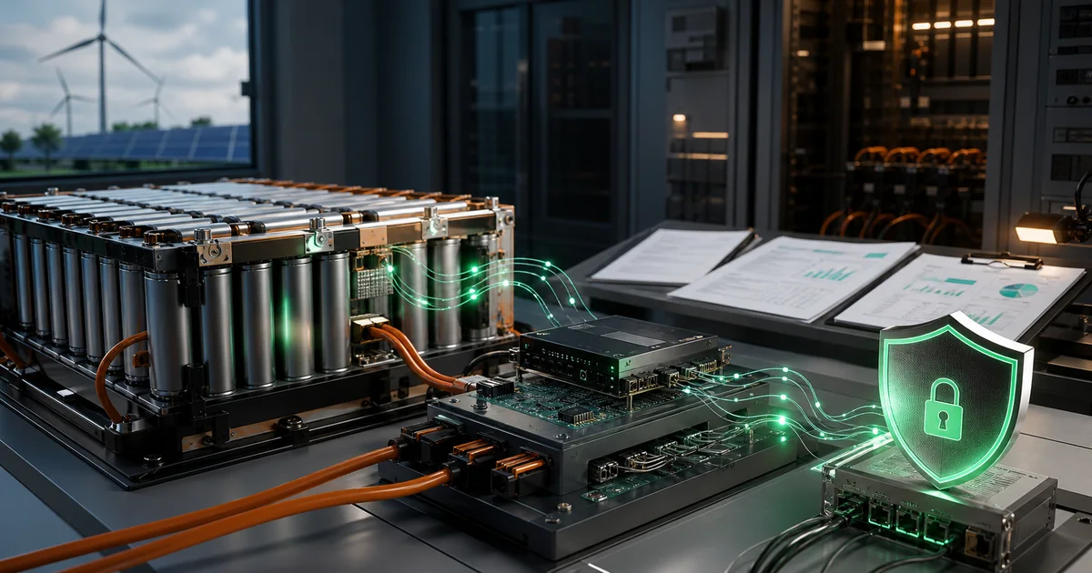
ISO 13849 Design Practice: From Principles to Implementation
In the engineering practice of functional safety, translating theoretical requirements into actionable technical solutions is the most critical challenge. ISO 13849-1 not only provides a complete evaluation framework but also offers a set of validated design principles and practical methods. This article will delve into these design practices, helping engineers build safety-related control systems that meet standard requirements in actual projects.
Design Process Overview
Before diving into specific design principles, we need to review the complete design process of ISO 13849. A standard safety-related control system (SRP/CS) design goes through four key phases:
┌─────────────────────────────────────────────────────────────────────┐
│                    SRP/CS Design Process                            │
├─────────────────────────────────────────────────────────────────────┤
│                                                                     │
│   ┌──────────┐    ┌──────────┐    ┌──────────┐    ┌──────────┐    │
│   │ 1.Define │───►│ 2.Design │───►│ 3.Evaluate│───►│ 4.Verify │    │
│   │ Safety  │    │Architecture│   │   PL     │    │ Validate │    │
│   │Function │    │           │    │          │    │          │    │
│   └──────────┘    └──────────┘    └──────────┘    └──────────┘    │
│        │               │               │               │          │
│        ▼               ▼               ▼               ▼          │
│   ┌──────────┐   ┌──────────┐   ┌──────────┐   ┌──────────┐      │
│   │  SRS    │   │ Select   │   │ Calculate│   │   Test   │      │
│   │ Document │   │ Category │   │Parameters│   │  Report  │      │
│   │ Define PLr│  │ Design   │   │ Check    │   │ Document │      │
│   └──────────┘   └──────────┘   └──────────┘   └──────────┘      │
│                                                                     │
└─────────────────────────────────────────────────────────────────────┘
This article will focus on the practical methods for Step 2 (Design Architecture) and Step 3 (Evaluate PL), which are the core links in transforming safety requirements into actual engineering implementations.
Hardware Safety Design Principles
Three-Layer Architecture of Safety Principles
ISO 13849-2 (Appendices A-D) divides safety principles into three levels, forming a complete design guidance system:
| Principle Type | English | Applicable Categories | Description |
|---|---|---|---|
| Basic Safety Principles | Basic Safety Principles | All categories | Fundamental requirements that must be followed |
| Well-tried Safety Principles | Well-tried Safety Principles | 1/2/3/4 | Validated design methods |
| Well-tried Components | Well-tried Components | 1 | Components with proven reliability |
This layered architecture means: all safety systems of any category must comply with basic safety principles, and as the category level increases, higher levels of validated principles and components need to be applied.
Basic Safety Principles: Foundation of All Designs
Basic safety principles are the foundation for building any safety system. Regardless of the target PL, these principles must be strictly followed.
Basic Requirements for Electrical Systems
Material selection needs to consider environmental factors:
- Temperature range: Operating temperature should be within the component’s rated range
- Humidity protection: Select appropriate protection rating based on application environment
- Corrosion protection: Use corrosion-resistant materials in harsh environments
Appropriate derating design is a key measure to improve reliability:
Derating design recommendations:

| Component Type | Derating Parameter | Recommended Derating Ratio |
|----------------|-------------------|---------------------------|
| Resistor | Power | 50% |
| Capacitor | Voltage | 30-50% |
| Semiconductor | Current/Voltage | 30-50% |
| Relay | Contact Current | 50% |
Design requirements for protection measures:
- Overvoltage protection: Use TVS tubes, voltage regulator tubes, or varistors
- Overcurrent protection: Fuses, circuit breakers, or current-limiting resistors
- Proper grounding: Low-impedance grounding path, avoid grounding loops
- Environmental protection: Appropriate IP rating, sealing, and coating
Basic Safety Principles Checklist
In actual design reviews, the following checklist can be used to ensure compliance:
┌─────────────────────────────────────────────────────────────────┐
│       Basic Safety Principles Checklist (Electrical Systems)     │
├─────────────────────────────────────────────────────────────────┤
│                                                                 │
│  Design Review Items:                                           │
│                                                                 │
│  □ Are all components used according to manufacturer specs?     │
│  □ Is appropriate derating design applied (voltage/current/power)?│
│  □ Are there appropriate overvoltage protection measures?       │
│  □ Are there appropriate overcurrent protection measures?       │
│  □ Is the grounding design compliant with standards?            │
│  □ Are EMC requirements considered?                            │
│  □ Are environmental conditions considered (temp, humidity, vibration)?│
│  □ Are connectors/terminals reliable?                          │
│  □ Is there mistake-proofing design?                           │
│  □ Is PCB layout compliant with safety requirements?           │
│                                                                 │
└─────────────────────────────────────────────────────────────────┘
Well-tried Safety Principles: Advanced Requirements for Category 1-4
When designing Category 1 to 4 systems, higher levels of validated safety principles need to be applied.
Force-Guided Contact Technology
This is the core technology of safety relays. Understanding it is crucial for designing high-reliability systems:
                    Force-Guided Contact Principle

    Normal State:                Fault State (Contact Welding):

    ┌──────────────┐            ┌──────────────┐
    │  NC ──/ ──   │            │  NC ──/ ──   │← Welded
    │      │       │            │      │       │
    │  ────┴────   │            │  ────┴────   │
    │      │       │            │      │       │
    │  NO ──┼──    │            │  NO ──┼──    │← Forced open
    │      │       │            │      │       │
    └──────────────┘            └──────────────┘

    Feature: All movable contacts are rigidly linked,
          when any contact welds, other contacts cannot close
Force-guided contacts ensure that even in the event of a fault, the system does not enter a dangerous state. This is one of the key technologies for implementing Category 1 and above systems.
Other Well-tried Safety Principles
| Principle | Description | Typical Applications |
|---|---|---|
| Short circuit protection | Use wiring techniques or monitoring to prevent short circuits | Bipolar wiring, current monitoring |
| Ground fault detection | Detect ground short circuits | Residual current protection |
| Redundant structure | Use multiple independent channels | Dual-channel safety circuits |
| Diverse technology | Use different technologies to achieve the same function | Different types of sensors |
| Periodic testing | Regularly check functions | Self-test procedures |
| Feedback loop | Output state feedback monitoring | Contact readback |
Well-tried Components: Reliability Foundation for Category 1
Well-tried components refer to components with extensive successful use experience in similar applications, or whose reliability has been proven through rigorous testing/analysis. For Category 1 systems, using well-tried components is a basic requirement.
Typical Well-tried Component Examples
| Component Type | Example | Validation Basis |
|---|---|---|
| Safety relay | Force-guided relay | IEC 61810-3 |
| Emergency stop button | Compliant with IEC 60947-5-5 | Extensive application history |
| Position switch | Compliant with IEC 60947-5-1 | Extensive application history |
| Safety light curtain | Compliant with IEC 61496 | Type test certification |
| Safety PLC | Compliant with IEC 61131-6 | Safety certification |
Using these validated components can significantly reduce design risk and improve system reliability.
Design Considerations for Fault Exclusion
Fault exclusion refers to techniques for reasonably excluding certain fault modes in design. This requires sufficient justification and documentation in technical documents.
Excludable Fault Types
| Fault Type | Exclusion Conditions |
|---|---|
| PCB trace breakage | Proper PCB design and protection |
| Resistor short circuit | Certain types of resistors |
| Connector single-point failure | Redundant connection design |
| Certain software faults | Validated software |
Important Note: Fault exclusion must have sufficient technical justification and cannot be arbitrarily excluded. During review, evaluators will pay special attention to the reasonableness of fault exclusions.
Subsystem Combination Techniques
Subsystem Series Model
In actual engineering, safety functions are often implemented by multiple subsystems in series. Understanding how to calculate the overall PL is key to design.
┌─────────────────────────────────────────────────────────────────────┐
│                    Subsystem Series Model                           │
│                                                                     │
│   ┌─────────────┐    ┌─────────────┐    ┌─────────────┐           │
│   │ Subsystem 1 │    │ Subsystem 2 │    │ Subsystem 3 │           │
│   │  (Sensor)   │───►│  (Safety PLC)│───►│  (Contactor)│           │
│   │   PL = d    │    │   PL = e    │    │   PL = c    │           │
│   └─────────────┘    └─────────────┘    └─────────────┘           │
│                                                                     │
│                    Overall PFH = PFH1 + PFH2 + PFH3                │
│                                                                     │
└─────────────────────────────────────────────────────────────────────┘
PFH Calculation Methods
Method 1: Known Subsystem PFH Values
When the PFH values of each subsystem are known, they can be directly added:
PFH_overall = PFH_1 + PFH_2 + ... + PFH_nCalculation Example:
| Subsystem | PFH |
|---|---|
| Light curtain sensor | 1.5×10⁻⁷/h |
| Safety PLC | 2.0×10⁻⁸/h |
| Contactor | 5.0×10⁻⁷/h |
PFH_overall = 1.5×10⁻⁷ + 2.0×10⁻⁸ + 5.0×10⁻⁷
        = 6.7×10⁻⁷/h

Corresponding PL = d (range: 10⁻⁷ to <10⁻⁶)
Method 2: Using Conservative Estimation
When exact PFH is unknown, the maximum PFH value corresponding to each PL can be used for conservative estimation:
| PL | Maximum PFH |
|---|---|
| a | 10⁻⁴/h |
| b | 10⁻⁵/h |
| c | 3×10⁻⁶/h |
| d | 10⁻⁶/h |
| e | 10⁻⁷/h |
PL Limitation for Series Systems
Important Rule: The PL of a series system cannot exceed the lowest PL subsystem!
Example:
Subsystem 1: PL d
Subsystem 2: PL c  ← Lowest
Subsystem 3: PL e

Overall PL ≤ c (cannot exceed the lowest subsystem PL)
This rule reflects the “bucket effect” in safety design—the shortest board determines the safety performance of the entire system.
Software Safety Requirements
Software Classification System
ISO 13849-1 divides software into two types, each with different requirements:
| Type | Abbreviation | Definition |
|---|---|---|
| Safety-related Embedded Software | SRESW | Provided by manufacturer, not modifiable by user |
| Safety-related Application Software | SRASW | Software configured by user according to application |
Software Language Classification
| Type | Abbreviation | Examples | Applicable Scenarios |
|---|---|---|---|
| Limited Variable Language | LVL | Ladder Diagram, Function Block Diagram | Safety PLC application programming |
| Full Variable Language | FVL | C, C++, Assembly | Embedded system development |
Software Requirements by PL Level
Different PL levels have different requirements for software development:
| Requirement | PL a-b | PL c | PL d | PL e |
|---|---|---|---|---|
| Software safety requirement specification | Mandatory | Mandatory | Mandatory | Mandatory |
| Software architecture design | Recommended | Mandatory | Mandatory | Mandatory |
| Modular design | Recommended | Recommended | Mandatory | Mandatory |
| Code review | Recommended | Mandatory | Mandatory | Mandatory |
| Unit testing | - | Recommended | Mandatory | Mandatory |
| Integration testing | Mandatory | Mandatory | Mandatory | Mandatory |
| Black box testing | Mandatory | Mandatory | Mandatory | Mandatory |
| Static analysis | - | Recommended | Mandatory | Mandatory |
| Formal methods | - | - | - | Recommended |
Software Development V Model
The V model is a classic framework for safety software development:
                        V Model Software Development

    Requirement Analysis ───────────────────────────► System Testing
        │                                               ▲
        │                                               │
        ▼                                               │
    Architecture Design ─────────────────────────► Integration Testing
        │                                               ▲
        │                                               │
        ▼                                               │
    Detailed Design ────────────────────────────► Unit Testing
        │                                               ▲
        │                                               │
        ▼                                               │
      Coding ────────────────────────────────────────┘


    Left side: Design and coding      Right side: Testing and verification
BMS Software Safety Practice
In BMS (Battery Management System) and other high-safety requirement applications, the following software diagnostic measures are standard practice:
Key Software Measures
| Measure | Purpose | Implementation Method |
|---|---|---|
| Watchdog | Detect program runaway | Independent hardware watchdog |
| Program flow monitoring | Detect execution sequence errors | Checkpoint verification |
| Memory verification | Detect RAM/Flash errors | CRC, ECC |
| Data range checking | Detect abnormal data | Reasonableness check |
| Time monitoring | Detect execution timeout | Cycle timer |
Diagnostic Coverage Reference
| Software Diagnostic Measure | Typical DC |
|---|---|
| Range check | 60% |
| Watchdog | 60% |
| Program flow monitoring | 70% |
| Dual-channel comparison | 90% |
| Memory CRC | 90% |
| Complete software diagnostic suite | 99% |
BMS Design Practical Case
Case Background
System Description: Industrial lithium battery pack BMS safety protection system
Battery Specifications:
- Voltage: 400V DC
- Capacity: 100Ah
- Application: Industrial energy storage/forklift
Safety Function Definition
| SF ID | Safety Function | PLr | Category Selection |
|---|---|---|---|
| SF1 | Overvoltage Protection (OVP) | e | 3/4 |
| SF2 | Undervoltage Protection (UVP) | c | 2/3 |
| SF3 | Overtemperature Protection (OTP) | d | 2/3 |
| SF4 | Overcurrent Protection (OCP) | d | 2/3 |
| SF5 | Insulation Monitoring (IMD) | d | 2/3 |
SF1 Overvoltage Protection Detailed Design
Function Description
- Trigger Condition: Any cell voltage > 4.25V
- Response Behavior: Cut off charging circuit
- Response Time: < 100ms
Architecture Design (Category 3)
┌─────────────────────────────────────────────────────────────────────────┐
│              SF1 Overvoltage Protection Architecture (Category 3)       │
│                                                                         │
│                          Input Part                                     │
│   ┌─────────────────────────────────────────────────────────────────┐  │
│   │  Voltage Sampling Channel 1         Voltage Sampling Channel 2   │  │
│   │  ┌─────┐  ┌─────┐  ┌─────┐       ┌─────┐  ┌─────┐  ┌─────┐    │  │
│   │  │Divider│─►│Filter│─►│ADC1 │       │Divider│─►│Filter│─►│ADC2 │    │  │
│   │  │Resistor│ │Circuit│ │     │       │Resistor│ │Circuit│ │     │    │  │
│   │  └─────┘  └─────┘  └──┬──┘       └─────┘  └─────┘  └──┬──┘    │  │
│   └─────────────────────────┼─────────────────────────────┼────────┘  │
│                             │                             │            │
│                             ▼                             ▼            │
│                          Logic Part                                     │
│   ┌─────────────────────────────────────────────────────────────────┐  │
│   │                                                                 │  │
│   │   ┌───────────────┐              ┌───────────────┐             │  │
│   │   │     MCU1      │◄──Cross Monitor──►│     MCU2      │             │  │
│   │   │               │              │               │             │  │
│   │   │ Voltage Calc  │              │ Voltage Calc  │             │  │
│   │   │ Threshold Compare│            │ Threshold Compare│             │  │
│   │   │ Result Output  │              │ Result Output  │             │  │
│   │   └───────┬───────┘              └───────┬───────┘             │  │
│   │           │                              │                     │  │
│   └───────────┼──────────────────────────────┼─────────────────────┘  │
│               │                              │                        │
│               ▼                              ▼                        │
│                          Output Part                                    │
│   ┌─────────────────────────────────────────────────────────────────┐  │
│   │                                                                 │  │
│   │   ┌───────────────┐              ┌───────────────┐             │  │
│   │   │    MOSFET1    │              │    MOSFET2    │             │  │
│   │   │  (Charging Circuit -) │              │  (Charging Circuit -) │             │  │
│   │   └───────────────┘              └───────────────┘             │  │
│   │           │                              │                     │  │
│   │           └──────────────┬───────────────┘                     │  │
│   │                          ▼                                      │  │
│   │                   Charging Circuit Open                         │  │
│   │                                                                 │  │
│   └─────────────────────────────────────────────────────────────────┘  │
│                                                                         │
└─────────────────────────────────────────────────────────────────────────┘
Parameter Calculation
MTTFd Calculation (Single Channel):
| Component | MTTFd | Source |
|---|---|---|
| Divider resistor×4 | 500 years | Derating design |
| Filter capacitor | 100 years | Appendix C |
| ADC | 200 years | MCU datasheet |
| MCU core | 100 years | Safety manual |
| MOSFET driver | 100 years | Appendix C |
| MOSFET | 50 years | Manufacturer data |
1/MTTFd = 1/500 + 1/100 + 1/200 + 1/100 + 1/100 + 1/50
        = 0.002 + 0.01 + 0.005 + 0.01 + 0.01 + 0.02
        = 0.057

MTTFd_Channel = 17.5 years → Medium
DCavg Calculation:
| Module | Diagnostic Measure | DC |
|---|---|---|
| Divider circuit | Range check + comparison verification | 90% |
| ADC | Cross comparison | 99% |
| MCU | Watchdog + memory CRC + program flow | 90% |
| MOSFET | Conduction state readback | 90% |
DCavg ≈ 92% → MediumCCF Scoring:
| Measure | Score |
|---|---|
| Physical separation (different ADCs, different driver circuits) | 15 |
| Electrical isolation (isolated sampling) | 20 |
| Diversity (optional: different algorithms) | 10 |
| Overvoltage protection | 15 |
| EMC measures | 20 |
| Periodic diagnostics | 10 |
| Total Score | 90 ≥ 65 ✓ |
PL Determination and Improvement
Check Category 3 chart:
- MTTFd = Medium
- DCavg = Medium
- PL = d
Problem: PL = d < PLr = e, requirement not met!
Improvement Solutions
Solution 1: Improve MTTFd to High
Use higher reliability MOSFET (MTTFd = 100 years) or redundant MOSFET design.
Solution 2: Improve DCavg to High
Add more diagnostics:
- Fully independent dual ADC + complete cross comparison
- Output dual readback
- Periodic test pulse
Solution 3: Upgrade to Category 4
Category 4 makes it easier to achieve PL e:
- Allows higher MTTFd limit (2500 years)
- Higher PL with same parameters
Final Design: Category 4
Improved parameters:
- MTTFd = High (using high-reliability components)
- DCavg = High (comprehensive diagnostics)
- CCF ≥ 65
Check Category 4 chart: PL = e ✓
Design Checklist and Validation
Hardware Design Checklist
┌─────────────────────────────────────────────────────────────────┐
│                    SRP/CS Hardware Design Checklist              │
├─────────────────────────────────────────────────────────────────┤
│                                                                 │
│  Project: _________________  Date: _________________            │
│  Safety Function: ___________________________________________    │
│  Target PLr: _____  Design Category: _____                      │
│                                                                 │
│  Basic Safety Principles:                                       │
│  □ Is component derating design appropriate?                    │
│  □ Are there appropriate overvoltage/overcurrent protections?   │
│  □ Is grounding design correct?                                 │
│  □ Are EMC measures sufficient?                                 │
│  □ Is environmental protection appropriate?                     │
│                                                                 │
│  Architecture Design:                                           │
│  □ Does it meet the requirements of the selected category?      │
│  □ Are redundant channels independent?                          │
│  □ Do diagnostic measures cover critical faults?                │
│  □ Are CCF measures sufficient?                                 │
│                                                                 │
│  Parameter Calculation:                                          │
│  □ Is MTTFd calculation complete?                               │
│  □ Is DCavg evaluation reasonable?                              │
│  □ Is CCF score ≥ 65?                                           │
│  □ Is achieved PL ≥ PLr?                                        │
│                                                                 │
│  Documentation:                                                  │
│  □ Is there a complete safety-related block diagram?            │
│  □ Is there FMEA/FMEDA analysis?                                │
│  □ Is fault exclusion justified?                                │
│                                                                 │
└─────────────────────────────────────────────────────────────────┘
Software Design Checklist
┌─────────────────────────────────────────────────────────────────┐
│                    SRP/CS Software Design Checklist              │
├─────────────────────────────────────────────────────────────────┤
│                                                                 │
│  Software Type: □ SRESW  □ SRASW                               │
│  Target PL: _____                                              │
│                                                                 │
│  Development Process:                                           │
│  □ Is there software safety requirement specification?          │
│  □ Is there software architecture design?                       │
│  □ Is modular design adopted?                                   │
│  □ Is there a coding standard?                                  │
│                                                                 │
│  Diagnostic Measures:                                           │
│  □ Is there a watchdog?                                         │
│  □ Is there program flow monitoring?                            │
│  □ Is there memory verification?                                │
│  □ Is there data range checking?                                │
│  □ Is there communication verification?                         │
│                                                                 │
│  Verification Testing:                                          │
│  □ Is there code review?                                        │
│  □ Is there unit testing?                                       │
│  □ Is there integration testing?                                │
│  □ Is there static analysis?                                    │
│                                                                 │
└─────────────────────────────────────────────────────────────────┘
Frequently Asked Questions
Q1: How to choose between Category 3 and Category 4 in BMS?
A: Depends on PLr and cost considerations:
- PLr ≤ d: Category 3 is usually sufficient
- PLr = e: Category 4 is easier to achieve, but Category 3 is also possible (requires high MTTFd and high DC)
- Cost sensitive: Category 3 has lower cost
- Highest safety: Category 4 is more conservative
Q2: Can BMS use commercial MCUs?
A: Yes, but requires:
- Select MCUs that comply with safety standards (such as those with IEC 60730 certification)
- Refer to the MCU’s safety manual
- Implement diagnostic measures required by the safety manual
- For high PL (d, e), safety MCUs are recommended (such as MPC5744P)
Q3: How to achieve high DC in software?
A: Combine multiple diagnostic measures:
- Watchdog (60%)
- Program flow monitoring (+70%)
- Memory CRC (+90%)
- Dual-channel comparison (90-99%)
- Comprehensive can reach 99%
Q4: When combining subsystems, why is the lowest PL the limiting factor?
A: Because the safety function is a complete chain, the weakest link determines the overall safety performance. For example:
- Sensor PL d + PLC PL e + Contactor PL c
- Even with a PL e component in the middle, the contactor PL c limits the overall to not exceed c
Q5: What documents does BMS need to prove compliance with ISO 13849?
A: Main documents include:
- Safety Requirement Specification (SRS)
- System architecture design document
- Safety-related block diagram
- FMEA/FMEDA analysis report
- MTTFd/DC/CCF calculation documents
- Software safety design document
- Verification test report
- Safety manual (user documentation)
Conclusion
ISO 13849 design practice is the key process of translating theoretical requirements into engineering implementation. By following basic safety principles, applying validated design methods, reasonably combining subsystems, and complementing with comprehensive software safety measures, engineers can build safety-related control systems that meet both standard requirements and actual application needs.
In high-safety requirement applications like BMS, Category 3/4 architecture combined with comprehensive diagnostic measures is an effective path to achieve PL d/e. More importantly, the entire design process requires complete technical documentation support, which is the foundation for proving compliance.
Functional safety is a process of continuous improvement. The cycle of design, verification, and improvement runs through the entire product lifecycle. Only by deeply understanding these design principles and continuously optimizing them in practice can we build truly reliable safety systems.
References
Standard Clauses
| Content | Standard Clause |
|---|---|
| Design principles | ISO 13849-1:2023 Chapter 6 |
| Software requirements | ISO 13849-1:2023 Chapter 7 |
| Basic safety principles | ISO 13849-2:2012 Appendices A-D |
| Circuit examples | IFA Report 2/2017e Chapter 8 |
Related Documents
- ISO 13849-1 Basic Framework and Core Concepts
- Performance Level and Category Detailed Explanation
- Key Parameter Calculation Methods
- MPC5744P Safety Manual (NXP)
- IEC 61508-3 (Software Requirements)
This article is part of the ISO 13849 standard interpretation series, covering the complete practical path from design principles to engineering implementation.